Real Equipment Pod Reference
In this section, we’ll discuss the technical considerations for designing custom real equipment pods in NETLAB+.
Note
You can skip this section if your pod design contains only virtual machines.
A real equipment pod contains one or more real lab devices. NETLAB+ provides console access to real equipment using its built-in CLI Terminal application and an Asynchronous Terminal Server (ATS). This provides an “air-gap” between equipment pods and campus networks. No routing between pod networks and campus is required.
- Lab Devices:
Real lab equipment that students will access, organized into pods. The pods depicted in the diagram above are the standard pods to support Cisco Networking Academy courses:
- Control Devices:
Infrastructure equipment that provides internal connectivity. These devices are not accessible to users.
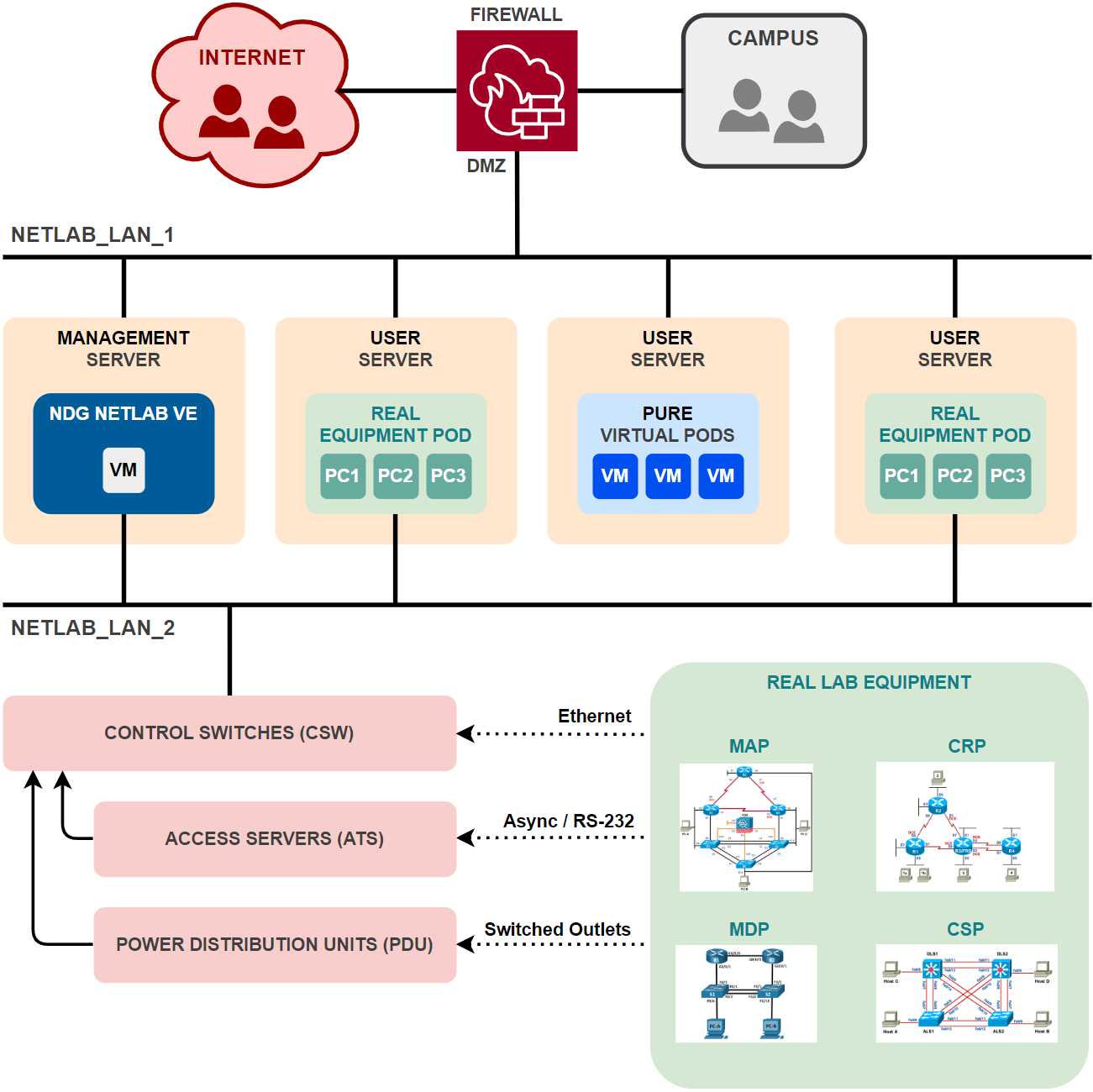
Networks
- NETLAB_LAN_1:
The primary network adapter that connects to the DMZ.
- NETLAB_LAN_2:
Internal connectivity between lab devices can be made with direct physical connections or through NETLAB+ control switches. The latter provides dynamic network flexibility for labs. In either case, the real equipment pods are isolated from the campus to maintain a safe sandbox for learners.
Communication between lab devices and virtual machines via control switches using VLANs to segregate traffic between pods. VLAns are dynamically assigned to control switch ports during lab reservations using VLAN maps.
Management traffic between NETLAB+ VE and control devices (VLAN 1, untagged)
Access Servers (ATS)
Access servers provide console connections to managed lab devices (lab routers, lab switches, and lab firewalls) so that users can access these devices from NETLAB+.
Each lab device in your pod design that requires console access by the pod user will consume one access server port.
The access server provides an air gap between lab devices and the production network.
The details of the access server are handled by NETLAB+ and are completely transparent to the user.
When a user clicks on a lab device on the topology image, NETLAB+ makes all the necessary connections through the NETLAB+ server and the access server automatically.
The NETLAB+ console sharing feature allows simultaneous access by multiple users to a lab device’s console port in multi-user reservations (team and ILT).
Power Distribution Units (PDU)
Power Distribution Units provide managed electrical power, allowing NETLAB+ and users to turn lab equipment ON and OFF. Each managed lab device in your pod design will consume one switched outlet on a PDU. Switched outlets also allow NETLAB+ to cycle power when required by automation, such as automatic password recovery of a Cisco lab device.

Control Switches (CSW)
Control switches provide four types of network connectivity:
Internal network connectivity between the NETLAB+ server, access servers, power distribution units, and other control switches.
Flexible connectivity between lab devices using VLANs.
A network path between real equipment and virtual machines running on VMware host servers.
A temporary network path for NETLAB+ to download IOS images to older Cisco lab devices in the event flash has been erased (or the correct image is not installed). This is not supported on newer Cisco devices, as they can recover images from read-only flash storage.
Control switch ports are categorized into lab device ports and control ports.
Control ports connect to supporting infrastructure that is not accessible to the user.
Lab device ports provide connectivity to user-accessible lab devices that are typically configured with an RS-232 async console connection.
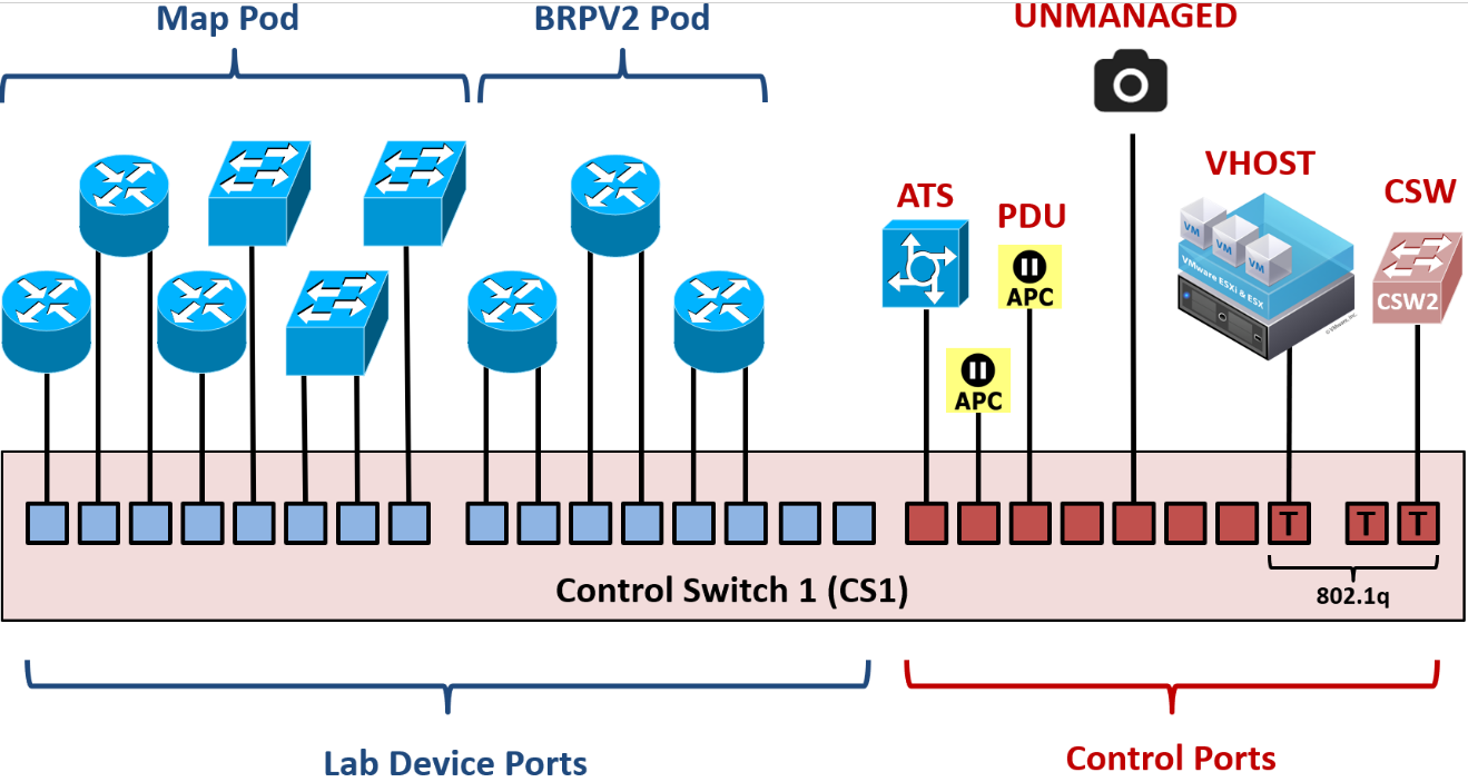
Control Ports
Control ports on a control switch provide the framework to interconnect NETLAB+, control devices, and other shared resources. These ports are designated by the administrator as one of the following roles:
Connection to an async terminal server (ATS)
Connection to another control switch (CSW)
Connection to a power distribution unit (PDU)
Connection to a virtual machine host (VHOST)
The NETLAB+ virtual appliance runs on a VHOST and communicates with the control switch via this type of control port.
Connection to an unmanaged device (manually configured)
Once the administrator designates a control port role, the port is configured by NETLAB with the proper settings for that role. For example, virtual host (VHOST) and control switch (CSW) port roles are automatically configured with 802.1Q and VLAN tags. Async terminal server (ATS) and power distribution unit (PDU) port roles are configured as non-trunking access ports in VLAN 1.
Lab Device Ports
Lab device ports connect real lab equipment to the NETLAB+ control switch. A single control switch can have pod ports for several pods. You may allocate more than one pod port for a lab device in order to simulate additional LAN segments. Both managed and unmanaged lab devices can be connected to pod ports.
Managed lab devices are device types that NETLAB+ can automate by temporarily taking over the console connection and issuing configuration commands. For example, NETLAB+ can perform a password recovery on certain types of Cisco devices. For a list of supported managed lab devices, please see the NDG website.
Unmanaged lab devices are physical devices that can be configured by the user through an asynchronous terminal server (RS-232) port but are not automated by NETLAB+. For example, a non-Cisco router can be configured using an RS-232 console port.
The pod design author determines how many control ports are required for each pod design and how those ports will connect to lab devices.
The NETLAB+ administrator may locate the lab device ports anywhere on a control switch.
Since the actual ports that will be used on the control switch are not known at design time, all control switch ports in a pod design are specified using relative port numbers (+0, +1, …, +5, etc.).
During normal operation, pod ports can be set to OFF or placed in unique or common VLANs to simulate one or more Ethernet segments required by the topology of the pod. This feature is called VLAN mapping and can be used to maximize the flexibility of a statically wired pod.
On older Cisco devices, NETLAB+ may temporarily place the device in VLAN 1 so that it can access the NETLAB+ internal TFTP server to obtain IOS images.
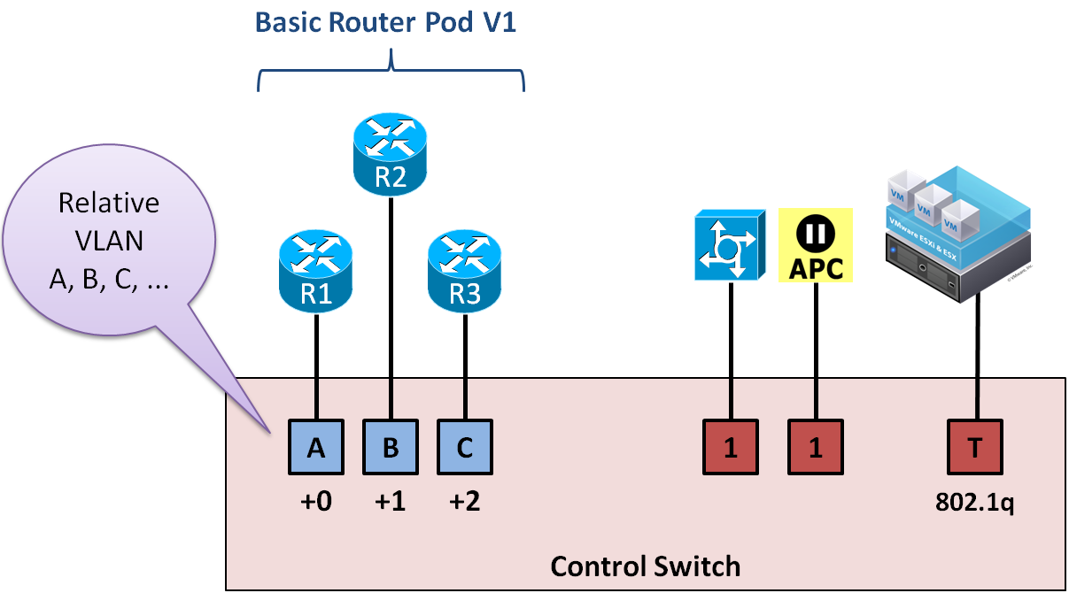
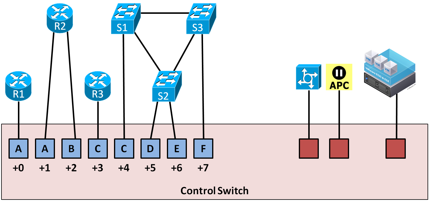
Control Ports Example 1
The NDG Basic Router Pod V1 is a simple pod design with one control switch connection per router. The pod design associates R1 with relative port +0, R2 with relative port +1, and R3 with relative port +2 (the blue ports). The actual port numbers cannot be determined at design time; these are determined when the NETLAB+ administrator creates an instance of the pod design and designates a control switch port for each of the three lab device ports.
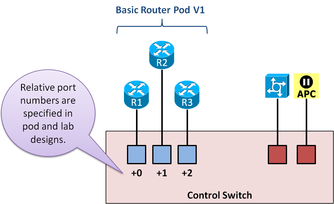
The pod also uses access server ports and switched outlets. Control ports (red) are used for the corresponding control devices, and no lab device ports (blue) are consumed in the pod design for these connections.
Control Ports Example 2
The NDG MAP pod provides 8 control switch ports for its lab devices. Router R2 and S2 were given two control switch connections. This decision was made after carefully looking through all the labs required to run on the pod and determining how LAN segments would best be simulated.
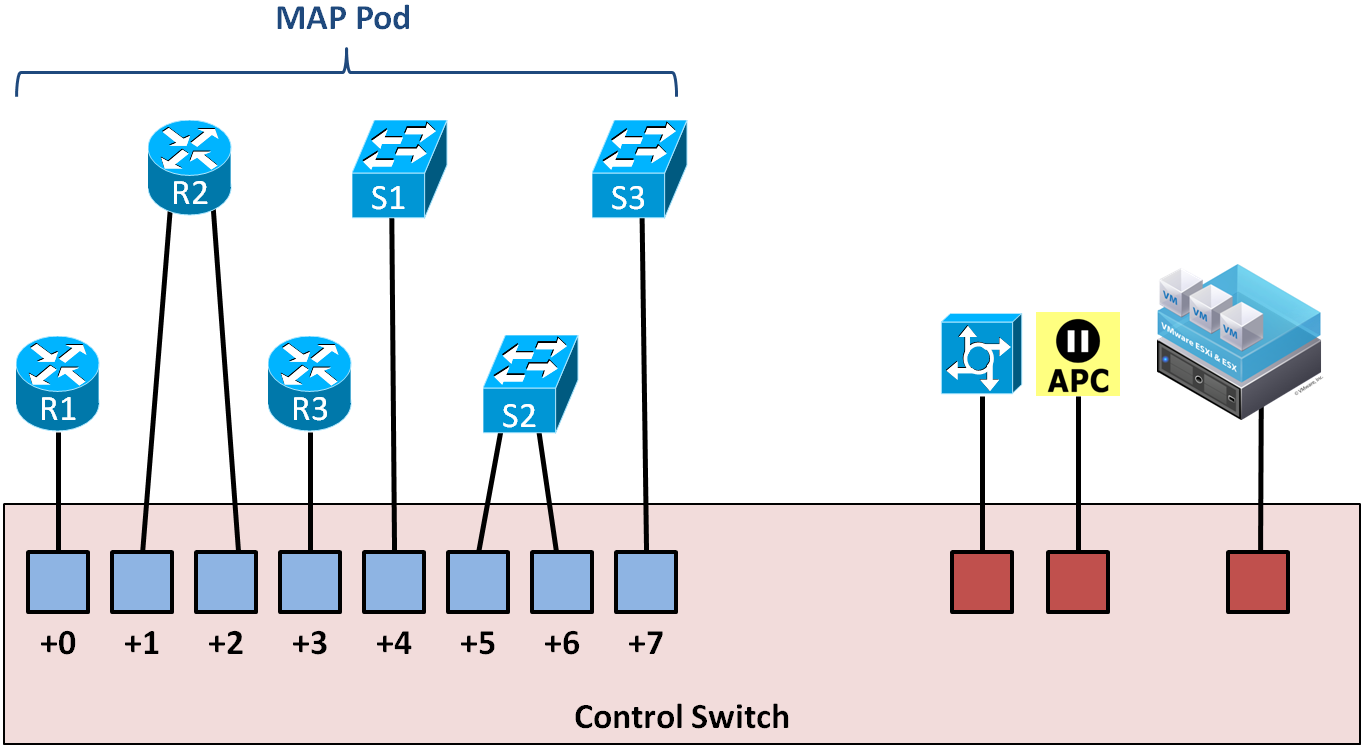
In addition to access server ports and switched outlets, the MAP pod also provides 3 virtual machines. The VMware host server for the 3 VMs connects to a VHOST port on the control switch; no lab device ports are consumed for the VMware host connection.
Control Switch VLAN Numbers
The following table shows the control switch VLAN numbering scheme used by NETLAB+.
VLAN(s) |
Purpose in NETLAB+ |
|---|---|
1 |
Management VLAN. Used for internal communication between the NETLAB+ server, control devices, and VMware servers. |
2-99 |
Reserved for NETLAB+. NETLAB+ may add or delete VLANs in this range. |
100-899 |
Reserved for NETLAB+ for pod dynamic VLAN maps. The maximum number of dynamic VLANs is 26 per pod and 800 per system. |
900-999 |
Reserved for customer special needs. NETLAB+ will not add or delete VLANs in this range. |
1000+ |
Reserved – do not use. |
Note
Control switches do not run the Cisco VLAN Trunking Protocol (VTP). NETLAB+ sets each control switch to VTP transparent mode during the initial switch configuration. It then uses SNMP to maintain a consistent VLAN database on each control switch. This method avoids VTP conflicts and other problems that can arise when lab switches are connected to control switches.
VLAN Mapping
VLAN mapping is a NETLAB+ feature that can significantly increase the number of labs that can be performed on a single pod design, thereby decreasing the overall cost of lab equipment.
During normal operation, pod ports can be set to OFF or placed in a VLAN to simulate one or more Ethernet segments required by the topology of the pod.
A VLAN map tells NETLAB+ which VLAN to assign to each control switch port at the beginning of a lab reservation.
A VLAN map can be provided for each lab exercise (these VLAN maps are specified in Lab Designer).
If a lab exercise does not provide a VLAN map, the default VLAN map specified in the pod design is used.
The actual VLAN numbers used by a pod are based on a pod’s ID, which is assigned by the NETLAB+ administrator. Since pod IDs cannot be determined at design time, the pod designer uses relative VLANs (A, B, C…, etc). The maximum number of VLANs per pod is 26. The maximum number of managed VLANs per NETLAB+ system is 800.
Recall that control switch port numbering in a pod design is also relative (+0, +1, +2, etc.). These ports are assigned to designated lab device ports on control switches by the NETLAB+ administrator. These ports need not be consecutive or confined to the same control switch in NETLAB+ version 22.
The number of VLANs allocated for the pod is the VLAN pool size. This value is set by the pod design author based on how many unique LAN segments are required.
Ports in a VLAN map do not need to be assigned to a VLAN. Alternatively, the port may be turned OFF or STATIC. A setting of STATIC instructs NETLAB+ not to manipulate the port. A static port might be configured as a trunk to a special unmanaged router or other special device.
VLAN maps may be easier to understand by example, so we have provided a few below.
VLAN Map Example 1
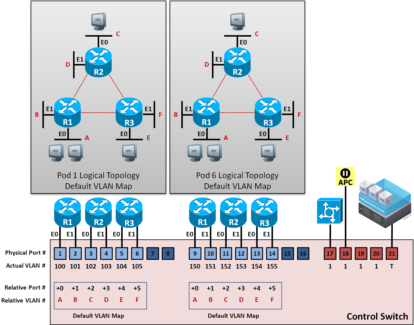
This example below shows the default VLAN map for a NETLAB+ Basic Router Pod (version 2). The VLAN pool size for this pod design is 6 (VLAN A to VLAN F). This provides enough VLANs so that each router port can be attached to a stub network.
Because each control switch port is placed in a unique VLAN, each LAN segment behaves as a separate routed segment, as shown in the Topology diagrams.
The PCs in these pods are virtual machines on a VMware host server. Discussed in the next section.
VLAN Map Example 2
The default VLAN map is normally applied to the pod at the beginning of a lab reservation. However, you may also create VLAN maps for each lab exercise (using Lab Designer). Each exercise may specify its own VLAN map or simply use the default VLAN map specified in the pod design.
By using VLAN maps in your lab exercises, you can make logical alterations to the lab topology without changing the cabling of the pod (which is always fixed). If the pod and lab designs utilize VLAN maps, it may be possible to perform many more labs than could be done with static mapping and/or direct connections between lab devices. By decreasing the number of physical lab topologies required, the potential cost of lab equipment to teach a curriculum is greatly reduced.
Consider the two pods below. Both pods are Basic Router Pod Version 2 pods and are physically wired as such. However, pod 6 has loaded an “HSRP” lab exercise that uses a dynamic VLAN map. The pod 6 topology will behave much differently than its pod 1 counterpart for the duration of the lab exercise. The lab exercise also presents the topology picture shown for pod 6, so the user actually sees the modified topology.

Lab Device Settings
This section applies to real equipment pods and hybrid pods.
Lab devices can be classified into 3 categories.
- Managed Lab Devices:
Real devices that lab users will actually configure during the lab. NETLAB+ automation drivers are provided for a variety of Cisco routers, switches, and firewalls.
- Generic Console Device:
Real equipment that users can connect to and configure but are not automated by NETLAB+ (except for user control over power). This allows devices that are not supported (or automated) by NDG to be used without an automation driver, provided they have a serial console port and can be accessed via an access server connection.
- Supporting Lab Devices:
Supporting real equipment that is not visible or configurable by the user.
Managed Lab Devices
The following table shows the automation features provided for supported managed lab devices. The table does not apply if the administrator chooses a Generic Console Device setting for the given lab device.
NETLAB+ Feature |
Cisco Routers |
Cisco Switches |
Cisco Firewalls |
|---|---|---|---|
Connect directly to the console port |
Yes |
Yes |
Yes |
Built-in terminal application to access device console ports |
Yes |
Yes |
Yes |
Share console with several users at the same time |
Yes |
Yes |
Yes |
Turn the device ON or OFF |
Yes |
Yes |
Yes |
Automatically load or save configuration files via the console port (does not rely on networking and TFTP) |
Yes |
Yes |
Yes |
Automatically perform password recovery |
Yes |
Yes |
Yes |
Reset device to a clean configuration upon request or at the end of the lab reservation |
Yes |
Yes |
Yes |
Automatically recover an image that has been erased from flash memory |
Partial |
No |
No |
Important
Automation relies on the capabilities of the managed lab device. Vendors may add or remove features from their devices (hardware or software) which may affect the automation features provided by NETLAB+.
Lab Routers
One connection to an access server port.
One connection to a switched outlet (i.e., APC device)
One or more connections to a control switch.
Refer to the three configuration scenarios below. LR1 is a lab router. LR1 has connections to the NETLAB+ control plane: access server (left), control switch (middle), and switch outlet device (right).
Example 1
The lowest numbered Ethernet (typically Fa0/0) port may be used to recover the router’s image should it be erased from flash on previously supported Cisco routers. Currently supported routers recover images from a read-only USB storage device, if capable.
During the lab, this port may be turned off or mapped dynamically to a VLAN on the control switch to simulate a LAN segment. Dynamic VLAN mapping is a powerful feature that may be used to alter the lab topology. This can be done for each lab exercise.
** Example 2**
Each Ethernet port connected to the control switch may participate in dynamic VLAN mapping. This technique can be used to create very flexible lab topologies from a single statically cabled pod.
** Example 3**
This configuration shows a direct connection between a lab router (LR1) and a lab switch (LS1).
Direct connections between lab devices are required to teach core switching concepts such as trunking, VTP, CDP, inter-VLAN routing, and port channeling. Direct connections preserve the nature of these protocols. A path through the control switch will not work in these scenarios.
Lab Switches
The following connections are required for each lab switch.
One console connection to an access server port.
One power connection to a switched outlet (i.e., APC device).
One connection to a control switch for every VMware virtual machine will appear as a directly attached PC.
Refer to the four configuration scenarios below. LS1 is a lab switch. LS1 has connections to the NETLAB+ control plane: access server (left), control switch (middle, recommended), and switch outlet device (right).
Example 1
Please note this configuration will not support flash recovery, should this feature be implemented for lab switches in the future. Therefore, we recommend one of the other configuration options below.
Example 2
If LS1 does not connect to other devices (such as VMware PCs) through the control switch, then the control switch connection can be turned off during the lab exercise. This connection also enhances NDG’s ability to perform diagnostics and troubleshooting on the lab switch.
Whenever a lab switch is connected to a control switch, additional configuration commands are required on the control switch to prevent unwanted spanning tree, trunking, and VTP side effects. This is explained in the following section.
Example 3
Direct connections between lab switches and other lab devices are required to teach core switching concepts such as trunking, VTP, CDP, inter-VLAN routing, and port channeling. Direct connections preserve the nature of these protocols. A path through the control switch will not work in these scenarios.
The connection between LS1 and the control switch is turned OFF during the lab. As in configuration 2, this is a management connection.
Whenever a lab switch is connected to a control switch, additional configuration commands are required on the control switch to prevent unwanted spanning tree, trunking, and VTP side effects. This is explained in the following section.
Example 4
Shows how virtual PCs can be tied to a lab switch via the control switch. To the lab user, each PC appears to be directly connected to ports on the lab switch.
Whenever a lab switch is connected to a control switch, additional configuration commands are required on the control switch to prevent unwanted spanning tree, trunking, and VTP side effects. This is explained in the following section.
–
Special Configuration for Pods Containing Lab Switches
Whenever a pod contains lab switches and ports on the lab switch connect to a control switch, NETLAB+ will apply additional commands to the control switch ports to prevent adverse interactions between the lab switch and control switches.
Danger
BEFORE CONNECTING LAB EQUIPMENT: The system administrator should perform the following steps in this order to prevent packet loops between control switches and lab switches.
Determine which access server (ATS) lines, control switch (CSW) lab ports, and power distribution outlets (PDU) will be assigned to the pod.
Ensure that all ATS, CSW, and PDU units are configured in NETLAB+.
Designate the control switch lab ports and configure them into the NETLAB+ free lab port pool. This step applies the necessary commands to the control switch lab ports to prevent packet loops. In NETLAB+ version 22, these commands are configured automatically.
Add the pod in NETLAB+.
Assign access server lines (ATS) to the pod.
Assign power distribution outlets (PDU) to the pod.
Assign control switch lab ports to the pod.
Now lab devices for the pod equipment can be safely connected to the designated control switch(es).
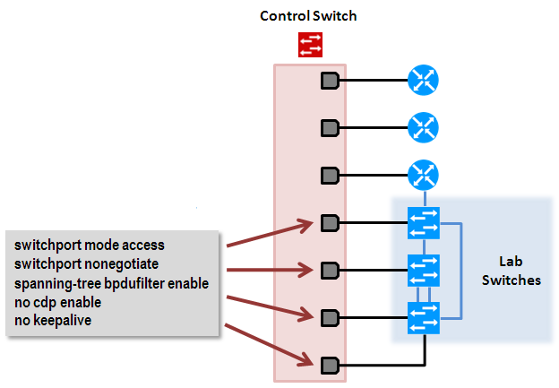
The following special commands (step 2) are configured on each control switch port that connects to a lab switch. They are provided for reference. You do not need to configure them manually on NETLAB+ version 22 systems.
- switchport mode access:
Prevents the link from becoming a trunk port.
The labs will not work as designed if the link between the control switch and the lab switch is trunking.
Trunking on ports that should be access ports, combined with BPDU filtering, creates loops that are not prevented by spanning trees.
- switchport nonegotiate:
Prevents the interface from sending DTP messages.
Disabling DTP messages is not critical but will hide the control switch’s MAC address from lab switches when users perform commands to see the CAM table.
- spanning-tree bpdufilter enable:
Instructs control switch port not to send and receive spanning tree BPDU frames to and from the lab switch.
Spanning tree in the lab must not mingle with the spanning tree on the control switch. This would cause several undesirable effects in both the lab and on the control switches.
- no cdp enable:
Disabling CDP is not critical but will hide the control switch from lab switch users performing CDP commands.
- no keepalive:
Prevents the interface from sending L2 keepalive messages.
Disabling L2 keepalives messages is not critical but will hide the control switch’s MAC address from lab switches when users performing commands to see the CAM table.
Here is an example configuration for a control switch control port that is connected to a lab switch:
interface FastEthernet0/X
description control port to lab switch LS1 port 7
switchport mode access
switchport nonegotiate
spanning-tree bpdu filter enable
no cdp enable
no keepalive
Special Configuration for Pods Containing Lab Switches
When connecting lab switches to control switches, special care must be taken not to create loops and other side effects. The commands and rules outlined in the previous help prevent this, but there is another rule that pod and lab design authors must follow to avoid trouble.
Explanation
Recall from the previous section that the spanning tree is intentionally disabled between the control switch (BPDU disabled) and lab switches. This creates a barrier between spanning tree domains.
a. Connections between lab switches and control switches are always non-trunking (switchport mode access, nonegotiate). Thus, VTP information is also isolated. That is, VLANs used on control switches are completely independent of VLANs that users may create on lab switches.
b. All packets between control switch and lab switches have no VLAN tagging.
By default, all lab switches ports will be placed in VLAN 1.
a. Any physical loops between lab switches will be prevented by the lab switch spanning tree domain.
b. However, spanning tree does not run between lab switch and control switch. Loop potential exists here.
These factors create the potential for loops to form between lab switches and control switches unless VLAN maps are properly constructed by pod and lab designers. By ensuring that control switch ports are placed on unique VLANs, you can ensure that interaction between control and lab switches will be loop-free, regardless of the configuration that takes place on the lab switches.
Example 1.
Our first example (below) shows a valid configuration. Each pod port connection on the control switch is placed in a unique VLAN (C, D, E, F). There is no possibility of looping through the control switch, regardless of how the user configures the lab switches.
Example 2.
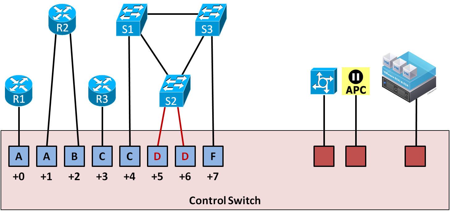
Our second example (below) shows an invalid VLAN map. Two ports share VLAN D. A loop will form between S2 and control switch. Broadcast traffic will quickly multiply and consume all the lab switches in this pod. More importantly, it will also consume the control switches with broadcast traffic.
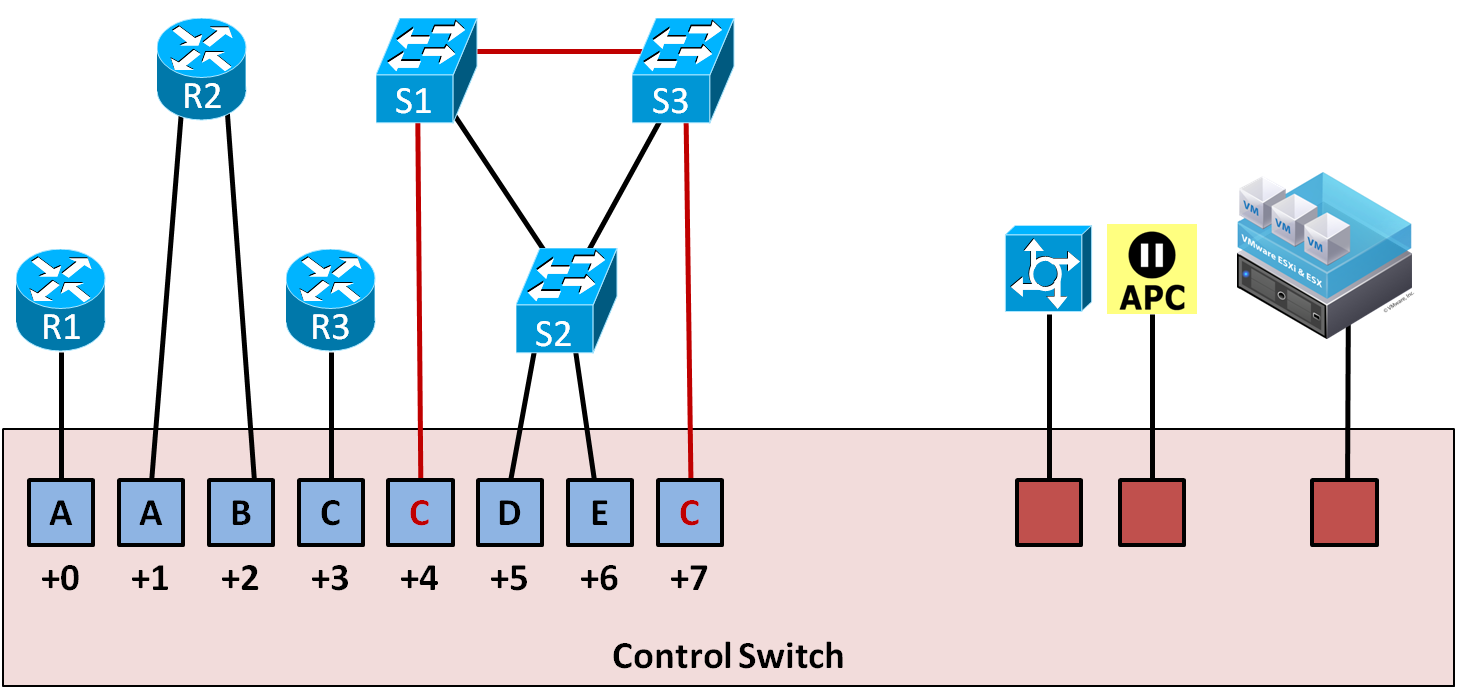
Example 3.
This scenario is also invalid for the same reason as example 2.
Lab Firewalls
The following connections are required for each lab firewall.
One connection to an access server port.
One connection to a switched outlet (i.e., APC device)
One connection from the lowest numbered built-in Ethernet port to the control switch (i.e., Ethernet0).
Refer to the three configuration scenarios below. LF1 is a lab firewall. LF1 has connections to the NETLAB+ control plane: access server (left), control switch (middle, recommended), and switch outlet device (right).
Lab Firewall Configuration 1
The lowest numbered Ethernet (typically Ethernet0) port may be used to recover the firewall’s image should it be erased from flash on previously supported Cisco firewalls. Currently supported firewalls recover images from a read-only USB storage device, if capable.
During the lab, this port may be turned off or mapped dynamically to a VLAN on the control switch to simulate a LAN segment. Dynamic VLAN mapping is a powerful feature that may be used to alter the lab topology. This can be done for each lab exercise.
Lab Firewall Configuration 2
Each Ethernet port connected to the control switch may participate in dynamic VLAN mapping. This technique can be used to create very flexible lab topologies from a single statically cabled pod.
Lab Firewall Configuration 3
Direct connections between lab firewalls and other lab devices are required to teach core firewall concepts such as routing, NAT, and access control lists. Direct connections preserve the nature of these protocols. A path through the control switch will not work in these scenarios.