Lab Design Guide
Document Version: 2020-04-17
Copyright © 2025 Network Development Group, Inc.
NETLAB+ is a registered trademark of Network Development Group, Inc.
VMware is a registered trademark of Broadcom, Inc.
Cisco, IOS, Cisco IOS, Networking Academy, CCNA, and CCNP are registered trademarks of Cisco Systems, Inc.
Introduction
This document is the NETLAB+ Lab Designer Guide for the virtual edition of NETLAB+.
NETLAB+ is a remote access solution that allows academic institutions to deliver a hands-on IT training experience with a wide variety of curriculum content options.
The training environment that NETLAB+ provides enables learners to schedule and complete lab exercises for information technology courses. NETLAB+ is a versatile solution for facilitating IT training in a variety of disciplines, including networking, virtualization, storage, and cybersecurity.
The material in this guide focuses on the functions and features of the Lab Designer feature of NETLAB+ VE, which provides a means of creating a series of custom laboratory exercises that may be made available for class use.
A lab design is a set of labs and related reference material that may include documents, images, and preset configuration files for each lab exercise. This data is stored in a Lab Design File. Lab design files are portable. They can be shared, exported, and installed on other NETLAB+ systems. A set of options and passwords control how the lab design can be used

[]Lab Design Files
A lab design file contains a set of labs and all related reference material. The following items are contained within a lab design file.
Lab Exercises
Documents
Images
Preset Configuration Files
[]Lab Exercises
Each lab design contains one or more lab exercises. Depending on the types of devices included in the lab topology, each lab exercise can:
Target a specific type of equipment pod.
Specify a document that contains instructions for completing the lab.
Specify a topology image with “clickable hotspots” for each device or PC.
Specify preset configuration files that are loaded into lab devices.
Specify a Dynamic VLAN Map to alter the lab topology.
Specify assessment options for online testing.
Specify alternate device names.
[]Documents
A document contains the instructions a user should follow to complete a lab. Users can view the document associated with a lab exercise by clicking the Show Content button in the lab access topology tab, or the preview lab link in the scheduler. The document must be a PDF file. The PDF format supports text, graphics, and precise formatting.

[]Images
Each lab exercise may specify an image that will appear in the lab access Topology tab. This is optional. By default, the image associated with the pod is used.
You may define clickable hotspots for devices and PCs shown on the image. A hotspot is an invisible rectangular area placed on top of a device in the image. When a user clicks on a hotspot, NETLAB+ will launch the appropriate viewer and connect to the device.

[]Configuration Files
You can create preset configuration files that can be loaded into routers, switches, and firewalls at the beginning of a lab exercise.
By default, users have the option to (1) load the preset configurations specified in the lab design, (2) load configuration files from a previous lab reservation, or (3) start clean with no configuration files loaded at all. However, you may require that a certain set of configuration files always be loaded at the beginning of a particular lab exercise. This feature is useful for assessment and troubleshooting labs.

[]Lab Designer Work Flow

The following steps outline the typical workflow of the lab design process.
Add Documents. Documents contain the instructions a user follows to complete a lab. A single document may be assigned to more than one lab exercise.
Add Images. A custom topology image can be displayed for each lab. A single image may be assigned to more than one lab exercise. By default, the pod’s topology is displayed.
Add Preset Configuration Files. Labs that include physical lab equipment can load preset configuration files into routers, switches, and firewalls at the beginning of a lab exercise. A single preset group may be assigned to more than one lab exercise.
Add Lab Exercises. The details of each lab exercise are defined in this step. Each lab may reference one of the documents, images, and preset configuration groups that were added in the previous steps.
Commit Build. When all the changes have been made, the build is committed. This prevents further changes to the current version of the lab design file and allows the lab design to be installed into the NETLAB+ database.
Install Build. Lab designer produces NLX files, which behave like software source code. To use the lab design, you must install (compile) the NLX file into the NETLAB+ database.
Add to Classes. Instructors must specifically grant access to an installed lab design by selecting the content.
[]Creating a New Lab Design
Lab Designer is accessed from the Manage dropdown for instructor accounts, or from the administrator home page. Simply click on the Lab Designer icon or link. The first time you use Lab Designer, you must agree to the terms of use.
The administrator and each instructor user are given a personal folder on the server. New lab designs (NLX files) are stored here. Click the Create New Lab Design button to begin a new lab design.

[] General Settings
The General Settings dialog will appear when you create a lab design. General settings are values that apply to the entire lab design. For guidance on completing the form, see the field descriptions below or select Help. After updating the fields, click OK.

Field Descriptions - Lab Design General Settings
Name: This required field is used to assign a name to the lab design. It may be helpful to indicate what course the lab will be used with, as part of the name or description.
Author’s Lab Design ID: A unique, human-readable identifier. Only the characters A-Z and 0-9 can be used. This value is appended to the Global Lab Design ID to create a unique identifier for the lab design. Please note, you cannot modify this value later. Example: “RIVUNWIRED”
Description: This optional field is used to describe the lab content. It may be helpful to indicate what course the lab will be used with, as part of the name or description.
Author: Optional field to indicate the author of the lab content.
Organization: Name of school or organization associated with the lab content.
Copyright: A place for a copyright notice (optional).
Support URL: A website URL containing additional information about the lab content (optional).
Note/Comment: Place to indicate any additional information about the lab design file, such as indicating what curriculum the lab design is being used to support.
Cloning: Enable the cloning checkbox to allow derivative works to be created from your lab design.
Access: The access setting affects which instructors and classes can use this lab design after it is installed on the system.
A private setting allows only the original installer to use the lab design in their classes.
A public setting allows all instructors on the system to use the lab design, provided that the system administrator specifically authorizes this. Future updates to an installed design are handled by the administrator or an appointed trustee. By default, the original installer is the trustee. Once the administrator marks the lab design public, only they can uninstall it.
[]Lab Designer Tabbed Interface
Once the general settings are entered, NETLAB+ will create a lab design file in your personal folder. All of the remaining tasks will be performed using the lab designer tabbed interface. The tabs are organized from left to right, in the same workflow order described in the previous section.
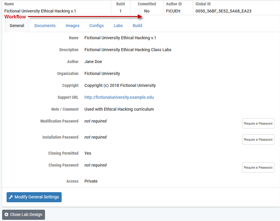
[] Enabling Password Protection
Password protection may be set for the lab design file. A Modification Password and Installation Password may be set as a requirement. If the option to permit cloning of the lab design was selected, a Cloning Password may also be set as a requirement. Select the appropriate Require a Password button(s) on the General page of the tabbed interface.
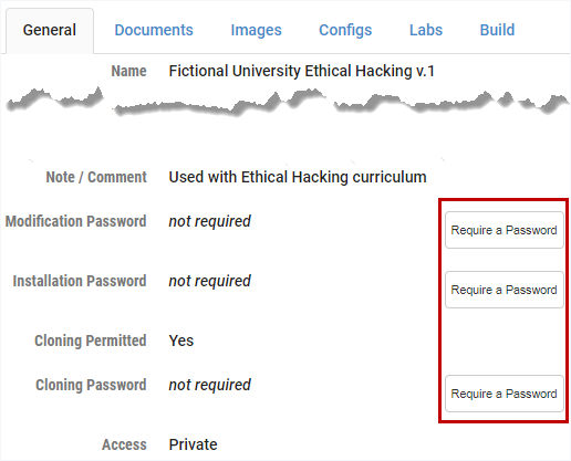
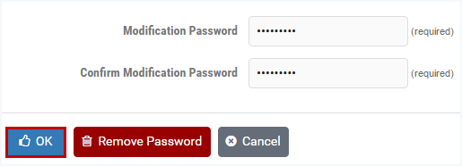
Here, a modification password is set. A modification password protects the design from being changed. This password will be required to modify the design. Enter the desired password twice and click OK. If a modification password is not required, click Remove Password.
If you set an installation password, this password will be required to install this lab design into the NETLAB+ database. Enter the desired password twice and click OK. If an installation password is not required, click Remove Password.

If you set a cloning password, this password will be required to create a clone (a copy) of the lab design. Enter the desired password twice and click OK. If a cloning password is not required, click Remove Password.

[]
Managing Documents
A document contains the instructions a user should follow to complete a lab. A single document may be assigned to more than one lab exercise. Users can view the document associated with a lab exercise by clicking the Show Content button in the lab access topology tab or the preview lab link in the scheduler. The document must be a PDF file. The PDF format supports text, graphics, and precise formatting.
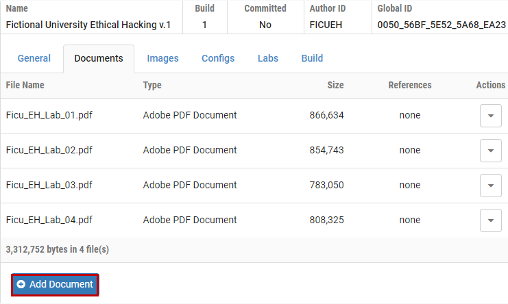
Select the Documents tab on the Lab Designer page. Any documents that have already been added to the lab design file will be listed in alphabetical order. To display the contents of the file, click on the file name. The type and size of the file are listed. The number of references is a count of the lab exercises that have been associated with the document. When a file is referenced by one or more lab exercises, it cannot be removed; the remove field will indicate in use.
[]
Adding a Document
Perform the following steps to add a document to a lab design file.
Select the Add Document
 button to add a document to the lab
design file.
button to add a document to the lab
design file.
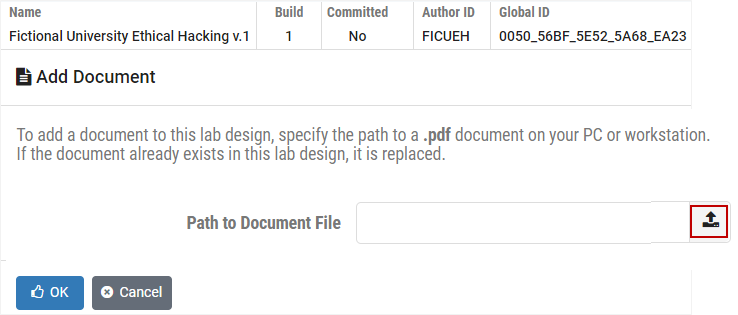
Select the file (the filename must end with the PDF extension) and click Open.
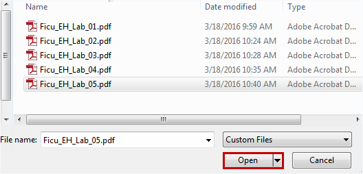
The filename is now listed on the Add Document page, click OK.
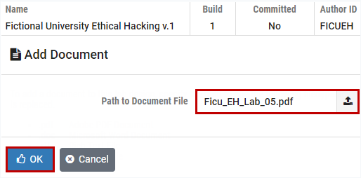
The document has been added to the list on the Documents tab.

[]Removing a Document
A document may be removed from the lab design if it is not designated as the lab document for a lab exercise. Labs that are not designated as a lab document for a lab exercise will have “none” displayed in the References column, as in the example below.
To remove a lab document, click the Actions dropdown for the lab and select Remove.

[]Managing Images
Each lab exercise may specify an image, which will appear in the lab access topology tab. This is optional. By default, the image associated with the pod is used.
Image files (GIF, JPEG, or PNG format) may be created and added to the lab design file to reflect exercise-specific information. An image may be associated with more than one lab exercise.
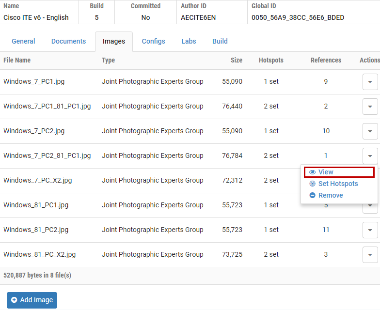
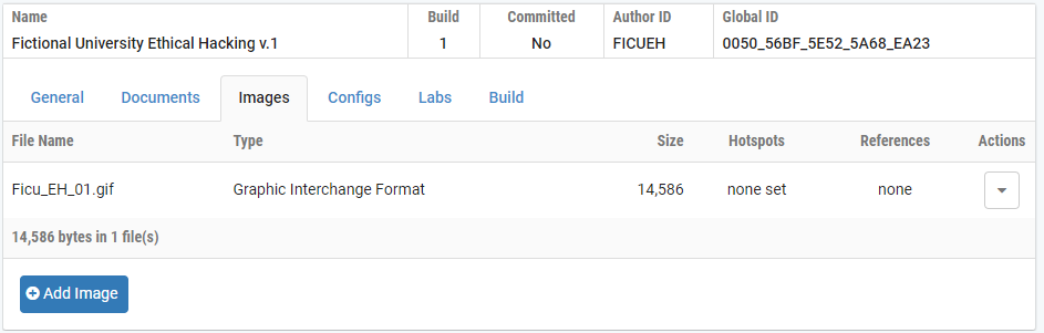
Select the Images tab on the Lab Designer page. Any images that have already been added to the lab design file will be listed in alphabetical order. The type and size of the file are listed. An image file may be referenced by one or more lab exercises. The number of references is a count of the lab exercises that have been associated with the image. To display the contents of an image file, select View on the Actions dropdown.
[]Adding an Image
Select the Add Image
button to add a document to the lab
design file.
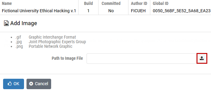
Select the file, which must end with one of the supported extensions (GIF, JPG, or PNG and click Open.
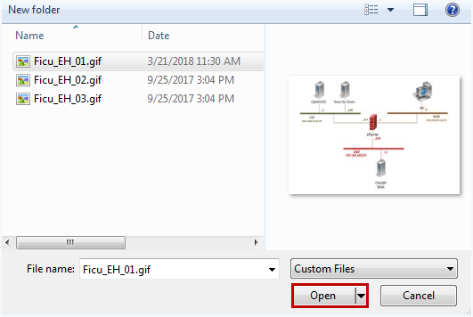
The filename is now listed on the Add Image page, click OK.

The image has been added to the list on the Images tab.
[]Defining Hotspots
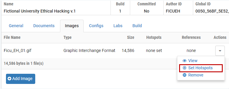
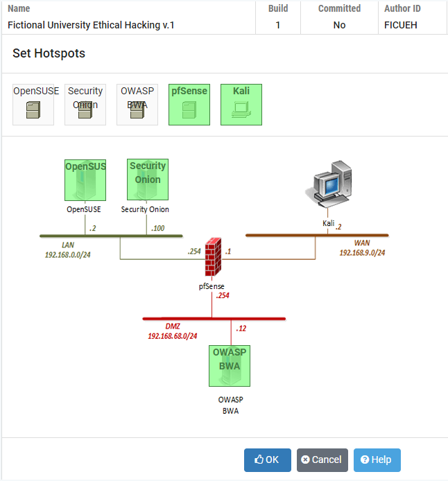
You may define clickable hotspots for devices and PCs shown on an image. A hotspot is an invisible rectangular area placed on top of a lab device or remote PC in the image. When a user clicks on a hotspot, NETLAB+ will launch the appropriate viewer and connect to the device. Perform the following steps to define hotspots on an image:
Select the file by clicking the Action dropdown and selecting Set Hotspots.
|

[]Removing an Image
An image may be removed from the lab design if it is not referenced as the topology image for a lab exercise. In the example below, the number of references indicates none for the first image. It may be removed by selecting Remove on the Actions dropdown.

[]Managing Preset Configuration Files
Lab designer allows you to create preset configuration files that can be loaded into routers, switches, and firewalls at the beginning of a lab exercise. By default, users have the option to:
Load the preset configurations specified in the lab design.
Load configuration files from a previous lab reservation.
Start clean with no configuration files loaded at all.
However, you may require that a certain set of configuration files always be loaded at the beginning of a particular lab exercise. This feature is useful for assessment and troubleshooting labs.
Configuration files for each device are organized into configuration folders, similar to the NETLAB+ file manager. A configuration folder and the files contained within can be assigned to one or more lab exercises. Please note, this is completely optional.
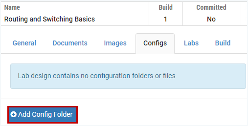
Select the Configs tab on the Lab Designer page. Any configuration folders that have already been added to the lab design file will be listed in alphabetical order. The number of references is a count of the lab exercises that are using the preset configuration. To view the contents of a folder, click the folder name or select the View option on the Actions dropdown.

[]Creating a Config Folder with a Specified Pod Type
Select the Add Config Folder button to add a configuration folder to the lab design file.
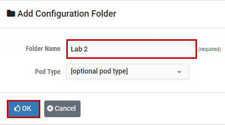
The Add Configuration Folder page will be displayed. Enter a name for the folder. If a Pod Type is selected, a configuration file for each configurable device in the topology will be created. Click OK.

In the example above, the pod type of “AE Multi-purpose Academy Pod” was selected. A tabbed interface will show the configuration files that have been set up for each device in the pod. You may type, or cut and paste IOS commands into each device-specific configuration file, by selecting the tab for each device. Here, commands have been entered into the R1 configuration file. To save the updated configuration files, select Update All.
[]Creating a Config Folder without Specifying a Pod Type
A configuration folder may also be created without designating a pod type, simply enter the folder name and then click OK (the Pod Type field is optional).
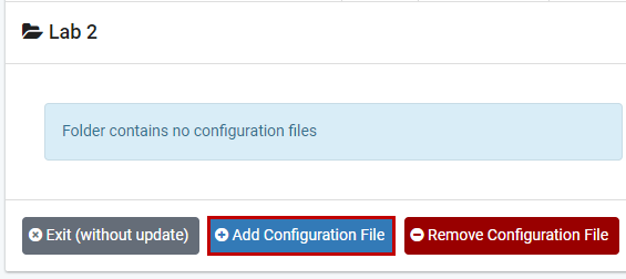
When the configuration folder name is selected on the Configs tab, the display will indicate that the folder is empty. Continue on to the next section, where we’ll discuss adding configuration files to the folder.

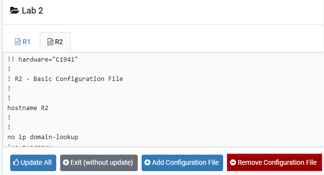
[]Adding a Single Configuration File to a Folder
Select the Add configuration file button to add a file to the folder.
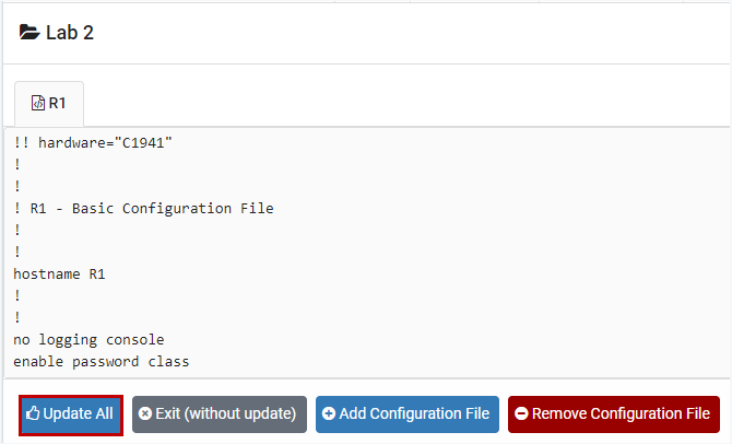
Enter the name of the device as it appears in the pod design and select OK.

A tabbed interface will show the configuration file with the device name. You may type, or cut and paste IOS commands into the configuration file. Here, commands have been entered into the R1 configuration file. To add configuration files for additional devices, select Add Configuration File and return to the previous step, creating a file for each device and adding IOS commands. When you are done, you must select the Update All button to save all changes and close the folder.
[]Removing a Single Configuration File
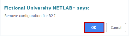
To remove a configuration file, select the file in the tabbed interface and then click the Remove Configuration File button.
Select OK to proceed with the deletion.
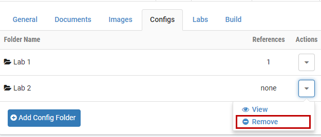
[]Removing a Configuration Folder
A configuration folder may be removed from the lab design if it has not been designated as the preset configuration for a lab exercise. In the example below, the first folder listed has been selected for one lab exercise, as indicated by the reference number listed in the references column. The second folder has not been referenced and may be removed by selecting the Remove option on the Actions dropdown.
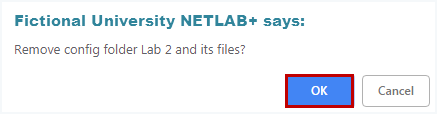
Select OK to proceed with the deletion.
[]
Interface Name Translation Feature
NETLAB+ interface name translation is an optional feature that allows configuration files to be loaded by NETLAB+, without errors, on pods with different lab device types, from the selection of lab devices supported by NETLAB+ VE. As a configuration is loaded, NETLAB+ will substitute the correct interface names for the actual device types being used (if necessary). To do this, NETLAB+ maintains a fixed table of interface names that should be present on each supported device model.
To enable interface name translation, perform the following two steps in each preset configuration file:
Add a comment line at the very top of the configuration file to specify the Device Type Identifier. Refer to the tables below to determine the appropriate Device Type Identifier, based on your selection of lab device. Note, there are two exclamation points (!!). Comment Format:
!! hardware=”device type identifier”
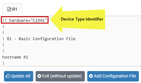
Adjust your interface commands to use the appropriate interface names. Interface names for routers, switches, and security devices are listed in the tables below. Do not abbreviate; the interface names must be typed EXACTLY as shown.
Router Interface Names |
|||
|---|---|---|---|
Device Type - Identifier |
Model |
Reference Interface |
Interface Name |
C1841 |
Cisco 1841 (S0/0/x) |
E0 |
FastEthernet0/0 |
E1 |
FastEthernet0/1 |
||
S0 |
Serial0/0/0 |
||
S1 |
Serial0/0/1 |
||
C1841-S01 |
Cisco 1841 (S0/1/x) |
E0 |
FastEthernet0/0 |
E1 |
FastEthernet0/1 |
||
S0 |
Serial0/1/0 |
||
S1 |
Serial0/1/1 |
||
C1841-NS |
Cisco 1841 (No Serial) |
E0 |
FastEthernet0/0 |
E1 |
FastEthernet0/1 |
||
C1941 |
Cisco 1941 (S0/0/x) |
E0 |
GigabitEthernet0/0 |
E1 |
GigabitEthernet0/1 |
||
S0 |
Serial0/0/0 |
||
S1 |
Serial0/0/1 |
||
C1941-S01 |
Cisco 1941 (S0/1/x) |
E0 |
GigabitEthernet0/0 |
E1 |
GigabitEthernet0/1 |
||
S0 |
Serial0/1/0 |
||
S1 |
Serial0/1/1 |
||
C1941-NS |
Cisco 1941 (No Serial) |
E0 |
GigabitEthernet0/0 |
E1 |
GigabitEthernet0/1 |
||
C2800-NS |
Cisco 2801/2811 (No Serial) |
E0 |
FastEthernet0/0 |
E1 |
FastEthernet0/1 |
||
C2800-S00 |
Cisco 2801/2811 (S0/0/x) |
E0 |
FastEthernet0/0 |
E1 |
FastEthernet0/1 |
||
C2800-S01 |
Cisco 2801/2811 (S0/1/x) |
E0 |
FastEthernet0/0 |
E1 |
FastEthernet0/1 |
||
S0 |
Serial0/1/0 |
||
S1 |
Serial0/1/1 |
||
C2800-S02 |
Cisco 2801/2811 (S0/2/x) |
E0 |
FastEthernet0/0 |
E1 |
FastEthernet0/1 |
||
S0 |
Serial0/2/0 |
||
S1 |
Serial0/2/1 |
||
C2800-S03 |
Cisco 2801/2811 (S0/3/x) |
E0 |
FastEthernet0/0 |
E1 |
FastEthernet0/1 |
||
S0 |
Serial0/3/0 |
||
S1 |
Serial0/3/1 |
||
C2821-NS |
Cisco 2821 (No Serial) |
E0 |
GigabitEthernet0/0 |
E1 |
GigabitEthernet0/1 |
||
C2821-S00 |
Cisco 2821 (S0/0/x) |
E0 |
GigabitEthernet0/0 |
E1 |
GigabitEthernet0/1 |
||
C2821-S01 |
Cisco 2821 (S0/1/x) |
E0 |
GigabitEthernet0/0 |
E1 |
GigabitEthernet0/1 |
||
S0 |
Serial0/1/0 |
||
S1 |
Serial0/1/1 |
||
C2821-S02 |
Cisco 2821 (S0/2/x) |
E0 |
GigabitEthernet0/0 |
E1 |
GigabitEthernet0/1 |
||
S0 |
Serial0/2/0 |
||
S1 |
Serial0/2/1 |
||
C2821-S03 |
Cisco 2821 (S0/3/x) |
E0 |
GigabitEthernet0/0 |
E1 |
GigabitEthernet0/1 |
||
S0 |
Serial0/3/0 |
||
S1 |
Serial0/3/1 |
||
C2900-NS |
Cisco 2901/2911 (No Serial) |
E0 |
GigabitEthernet0/0 |
E1 |
GigabitEthernet0/1 |
||
C2900-S00 |
Cisco 2901/2911 (S0/0/x) |
E0 |
GigabitEthernet0/0 |
E1 |
GigabitEthernet0/1 |
||
S0 |
Serial0/0/0 |
||
S1 |
Serial0/0/1 |
||
C2900-S01 |
Cisco 2901/2911 (S0/1/x) |
E0 |
GigabitEthernet0/0 |
E1 |
GigabitEthernet0/1 |
||
S0 |
Serial0/1/0 |
||
S1 |
Serial0/1/1 |
||
C2900-S02 |
Cisco 2901/2911 (S0/2/x) |
E0 |
GigabitEthernet0/0 |
E1 |
GigabitEthernet0/1 |
||
S0 |
Serial0/2/0 |
||
S1 |
Serial0/2/1 |
||
C2900-S03 |
Cisco 2901/2911 (S0/3/x) |
E0 |
GigabitEthernet0/0 |
E1 |
GigabitEthernet0/1 |
||
S0 |
Serial0/3/0 |
||
S1 |
Serial0/3/1 |
||
C4431-NS |
Cisco 4431 (No Serial) |
E0 |
GigabitEthernet0/0 |
E1 |
GigabitEthernet0/1 |
||
C4331-S01 |
Cisco 4331 (S0/1/x) |
E0 |
GigabitEthernet0/0 |
E1 |
GigabitEthernet0/1 |
||
S0 |
Serial0/1/0 |
||
S1 |
Serial0/1/1 |
||
C4331-S02 |
Cisco 4331 (S0/2/x) |
E0 |
GigabitEthernet0/0 |
E1 |
GigabitEthernet0/1 |
||
S0 |
Serial0/2/0 |
||
S1 |
Serial0/2/1 |
||
C4321-NS |
Cisco 4321 (No Serial) |
E0 |
GigabitEthernet0/0 |
E1 |
GigabitEthernet0/1 |
||
C4321-S01 |
Cisco 4321 (S0/1/x) |
E0 |
GigabitEthernet0/0 |
E1 |
GigabitEthernet0/1 |
||
S0 |
Serial0/1/0 |
||
S1 |
Serial0/1/1 |
||
C4321-S02 |
Cisco 4321 (S0/2/x) |
E0 |
GigabitEthernet0/0 |
E1 |
GigabitEthernet0/1 |
||
S0 |
Serial0/2/0 |
||
S1 |
Serial0/2/1 |
||
C4221-NS |
Cisco 4221 (No Serial) |
E0 |
GigabitEthernet0/0 |
E1 |
GigabitEthernet0/1 |
||
C4221-S01 |
Cisco 4221 (S0/1/x) |
E0 |
GigabitEthernet0/0 |
E1 |
GigabitEthernet0/1 |
||
S0 |
Serial0/1/0 |
||
S1 |
Serial0/1/1 |
||
C4221-S02 |
Cisco 4221 (S0/2/x) |
E0 |
GigabitEthernet0/0 |
E1 |
GigabitEthernet0/1 |
||
S0 |
Serial0/2/0 |
||
S1 |
Serial0/2/1 |
Switch Interface Names |
|||
|---|---|---|---|
Device Type - Identifier |
Model |
Reference Interface |
Interface Name |
C2950-12 |
Cisco C2950-12/C2950G-12-EI |
E1 |
FastEthernet0/1 |
E2 |
FastEthernet0/2 |
||
E3 |
FastEthernet0/3 |
||
E4 |
FastEthernet0/4 |
||
E5 |
FastEthernet0/5 |
||
E6 |
FastEthernet0/6 |
||
E7 |
FastEthernet0/7 |
||
E8 |
FastEthernet0/8 |
||
E9 |
FastEthernet0/9 |
||
E10 |
FastEthernet0/10 |
||
E11 |
FastEthernet0/11 |
||
E12 |
FastEthernet0/12 |
||
U1 |
GigabitEthernet0/1 |
||
U2 |
GigabitEthernet0/2 |
||
U3 |
GigabitEthernet0/3 |
||
U4 |
GigabitEthernet0/4 |
||
C2950-24 |
Cisco C2950-24/C2950G-24-EI/C2950T-24 |
E1 |
FastEthernet0/1 |
E2 |
FastEthernet0/2 |
||
E3 |
FastEthernet0/3 |
||
E4 |
FastEthernet0/4 |
||
E5 |
FastEthernet0/5 |
||
E6 |
FastEthernet0/6 |
||
E7 |
FastEthernet0/7 |
||
E8 |
FastEthernet0/8 |
||
E9 |
FastEthernet0/9 |
||
E10 |
FastEthernet0/10 |
||
E11 |
FastEthernet0/11 |
||
E12 |
FastEthernet0/12 |
||
E13 |
FastEthernet0/13 |
||
E14 |
FastEthernet0/14 |
||
E15 |
FastEthernet0/15 |
||
E16 |
FastEthernet0/16 |
||
E17 |
FastEthernet0/17 |
||
E18 |
FastEthernet0/18 |
||
E19 |
FastEthernet0/19 |
||
E20 |
FastEthernet0/20 |
||
E21 |
FastEthernet0/21 |
||
E22 |
FastEthernet0/22 |
||
E23 |
FastEthernet0/23 |
||
E24 |
FastEthernet0/24 |
||
U1 |
GigabitEthernet0/1 |
||
U2 |
GigabitEthernet0/2 |
||
U3 |
GigabitEthernet0/3 |
||
U4 |
GigabitEthernet0/4 |
||
C2950G-48-EI |
Cisco C2950-48-EI |
E1 |
FastEthernet0/1 |
E2 |
FastEthernet0/2 |
||
E3 |
FastEthernet0/3 |
||
E4 |
FastEthernet0/4 |
||
E5 |
FastEthernet0/5 |
||
E6 |
FastEthernet0/6 |
||
E7 |
FastEthernet0/7 |
||
E8 |
FastEthernet0/8 |
||
E9 |
FastEthernet0/9 |
||
E10 |
FastEthernet0/10 |
||
E11 |
FastEthernet0/11 |
||
E12 |
FastEthernet0/12 |
||
E13 |
FastEthernet0/13 |
||
E14 |
FastEthernet0/14 |
||
E15 |
FastEthernet0/15 |
||
E16 |
FastEthernet0/16 |
||
E17 |
FastEthernet0/17 |
||
E18 |
FastEthernet0/18 |
||
E19 |
FastEthernet0/19 |
||
E20 |
FastEthernet0/20 |
||
E21 |
FastEthernet0/21 |
||
E22 |
FastEthernet0/22 |
||
E23 |
FastEthernet0/23 |
||
E24 |
FastEthernet0/24 |
||
E25 |
FastEthernet0/25 |
||
E26 |
FastEthernet0/26 |
||
E27 |
FastEthernet0/27 |
||
E28 |
FastEthernet0/28 |
||
E29 |
FastEthernet0/29 |
||
E30 |
FastEthernet0/30 |
||
E31 |
FastEthernet0/31 |
||
E32 |
FastEthernet0/32 |
||
E33 |
FastEthernet0/33 |
||
E34 |
FastEthernet0/34 |
||
E35 |
FastEthernet0/35 |
||
E36 |
FastEthernet0/36 |
||
E37 |
FastEthernet0/37 |
||
E38 |
FastEthernet0/38 |
||
E39 |
FastEthernet0/39 |
||
E40 |
FastEthernet0/40 |
||
E41 |
FastEthernet0/41 |
||
E42 |
FastEthernet0/42 |
||
E43 |
FastEthernet0/43 |
||
E44 |
FastEthernet0/44 |
||
E45 |
FastEthernet0/45 |
||
E46 |
FastEthernet0/46 |
||
E47 |
FastEthernet0/47 |
||
E48 |
FastEthernet0/48 |
||
U1 |
GigabitEthernet0/1 |
||
U2 |
GigabitEthernet0/2 |
||
U3 |
GigabitEthernet0/3 |
||
U4 |
GigabitEthernet0/4 |
||
C2960 |
Cisco 2960 |
E1 |
FastEthernet0/1 |
E2 |
FastEthernet0/2 |
||
E3 |
FastEthernet0/3 |
||
E4 |
FastEthernet0/4 |
||
E5 |
FastEthernet0/5 |
||
E6 |
FastEthernet0/6 |
||
E7 |
FastEthernet0/7 |
||
E8 |
FastEthernet0/8 |
||
E9 |
FastEthernet0/9 |
||
E10 |
FastEthernet0/10 |
||
E11 |
FastEthernet0/11 |
||
E12 |
FastEthernet0/12 |
||
E13 |
FastEthernet0/13 |
||
E14 |
FastEthernet0/14 |
||
E15 |
FastEthernet0/15 |
||
E16 |
FastEthernet0/16 |
||
E17 |
FastEthernet0/17 |
||
E18 |
FastEthernet0/18 |
||
E19 |
FastEthernet0/19 |
||
E20 |
FastEthernet0/20 |
||
E21 |
FastEthernet0/21 |
||
E22 |
FastEthernet0/22 |
||
E23 |
FastEthernet0/23 |
||
E24 |
FastEthernet0/24 |
||
U1 |
GigabitEthernet0/1 |
||
U2 |
GigabitEthernet0/2 |
||
U3 |
GigabitEthernet0/3 |
||
U4 |
GigabitEthernet0/4 |
||
C3550-12 |
Cisco C3550-12G/C3550-12T |
E1 |
GigabitEthernet0/1 |
E2 |
GigabitEthernet0/2 |
||
E3 |
GigabitEthernet0/3 |
||
E4 |
GigabitEthernet0/4 |
||
E5 |
GigabitEthernet0/5 |
||
E6 |
GigabitEthernet0/6 |
||
E7 |
GigabitEthernet0/7 |
||
E8 |
GigabitEthernet0/8 |
||
E9 |
GigabitEthernet0/9 |
||
E10 |
GigabitEthernet0/10 |
||
E11 |
GigabitEthernet0/11 |
||
E12 |
GigabitEthernet0/12 |
||
U1 |
GigabitEthernet1/0/1 |
||
U2 |
GigabitEthernet1/0/2 |
||
U3 |
GigabitEthernet1/0/3 |
||
U4 |
GigabitEthernet1/0/4 |
||
C3550-24 |
Cisco C3550-24-EMI/C3550-24-SMI |
E1 |
FastEthernet0/1 |
E2 |
FastEthernet0/2 |
||
E3 |
FastEthernet0/3 |
||
E4 |
FastEthernet0/4 |
||
E5 |
FastEthernet0/5 |
||
E6 |
FastEthernet0/6 |
||
E7 |
FastEthernet0/7 |
||
E8 |
FastEthernet0/8 |
||
E9 |
FastEthernet0/9 |
||
E10 |
FastEthernet0/10 |
||
E11 |
FastEthernet0/11 |
||
E12 |
FastEthernet0/12 |
||
E13 |
FastEthernet0/13 |
||
E14 |
FastEthernet0/14 |
||
E15 |
FastEthernet0/15 |
||
E16 |
FastEthernet0/16 |
||
E17 |
FastEthernet0/17 |
||
E18 |
FastEthernet0/18 |
||
E19 |
FastEthernet0/19 |
||
E20 |
FastEthernet0/20 |
||
E21 |
FastEthernet0/21 |
||
E22 |
FastEthernet0/22 |
||
E23 |
FastEthernet0/23 |
||
E24 |
FastEthernet0/24 |
||
U1 |
GigabitEthernet0/1 |
||
U2 |
GigabitEthernet0/2 |
||
U3 |
GigabitEthernet0/3 |
||
U4 |
GigabitEthernet0/4 |
||
C3560 |
Cisco 3560 |
E1 |
FastEthernet0/1 |
E2 |
FastEthernet0/2 |
||
E3 |
FastEthernet0/3 |
||
E4 |
FastEthernet0/4 |
||
E5 |
FastEthernet0/5 |
||
E6 |
FastEthernet0/6 |
||
E7 |
FastEthernet0/7 |
||
E8 |
FastEthernet0/8 |
||
E9 |
FastEthernet0/9 |
||
E10 |
FastEthernet0/10 |
||
E11 |
FastEthernet0/11 |
||
E12 |
FastEthernet0/12 |
||
E13 |
FastEthernet0/13 |
||
E14 |
FastEthernet0/14 |
||
E15 |
FastEthernet0/15 |
||
E16 |
FastEthernet0/16 |
||
E17 |
FastEthernet0/17 |
||
E18 |
FastEthernet0/18 |
||
E19 |
FastEthernet0/19 |
||
E20 |
FastEthernet0/20 |
||
E21 |
FastEthernet0/21 |
||
E22 |
FastEthernet0/22 |
||
E23 |
FastEthernet0/23 |
||
E24 |
FastEthernet0/24 |
||
U1 |
GigabitEthernet0/1 |
||
U2 |
GigabitEthernet0/2 |
||
U3 |
GigabitEthernet0/3 |
||
U4 |
GigabitEthernet0/4 |
||
E1 |
GigabitEthernet1/0/1 |
||
E2 |
GigabitEthernet1/0/2 |
||
E3 |
GigabitEthernet1/0/3 |
||
E4 |
GigabitEthernet1/0/4 |
||
E5 |
GigabitEthernet1/0/5 |
||
E6 |
GigabitEthernet1/0/6 |
||
E7 |
GigabitEthernet1/0/7 |
||
E8 |
GigabitEthernet1/0/8 |
||
E9 |
GigabitEthernet1/0/9 |
||
E10 |
GigabitEthernet1/0/10 |
||
E11 |
GigabitEthernet1/0/11 |
||
E12 |
GigabitEthernet1/0/12 |
||
E13 |
GigabitEthernet1/0/13 |
||
E14 |
GigabitEthernet1/0/14 |
||
E15 |
GigabitEthernet1/0/15 |
||
E16 |
GigabitEthernet1/0/16 |
||
E17 |
GigabitEthernet1/0/17 |
||
E18 |
GigabitEthernet1/0/18 |
||
E19 |
GigabitEthernet1/0/19 |
||
E20 |
GigabitEthernet1/0/20 |
||
E21 |
GigabitEthernet1/0/21 |
||
E22 |
GigabitEthernet1/0/22 |
||
E23 |
GigabitEthernet1/0/23 |
||
E24 |
GigabitEthernet1/0/24 |
||
U1 |
GigabitEthernet1/1/1 |
||
U2 |
GigabitEthernet1/1/2 |
||
U3 |
GigabitEthernet1/1/3 |
||
U4 |
GigabitEthernet1/1/4 |
Security Device Interface Names |
|||
|---|---|---|---|
Device Type - Identifier |
Model |
Reference Interface |
Interface Name |
ASA5505 |
Cisco ASA-5505 |
E0 |
Ethernet0/0 |
E1 |
Ethernet0/1 |
||
E2 |
Ethernet0/2 |
||
E3 |
Ethernet0/3 |
||
E4 |
Ethernet0/4 |
||
E5 |
Ethernet0/5 |
||
E6 |
Ethernet0/6 |
||
E7 |
Ethernet0/7 |
||
ASA5506 |
Cisco ASA-5506 |
E0 |
GigabitEthernet1/1 |
E1 |
GigabitEthernet1/2 |
||
E2 |
GigabitEthernet1/3 |
||
E3 |
GigabitEthernet1/4 |
||
E4 |
GigabitEthernet1/5 |
||
E5 |
GigabitEthernet1/6 |
||
E6 |
GigabitEthernet1/7 |
||
E7 |
GigabitEthernet1/8 |
||
ASA5510 |
Cisco ASA-5510 |
E0 |
Ethernet0/0 |
E1 |
Ethernet0/1 |
[]Managing Lab Exercises
Each lab design contains one or more lab exercises. Each lab exercise appears in the lab catalog when a user schedules a lab, provided that the pod type specified in the lab design is available. Each lab exercise can:
Target a specific type of equipment pod.
Specify a document, which contains instructions for completing the lab.
Specify a topology image with “clickable hotspots” for each device or PC.
Specify preset configuration files, which are loaded into lab devices.
Specify a Dynamic VLAN Map to alter the lab topology.
Specify assessment options for online testing.
Specify alternate device names.
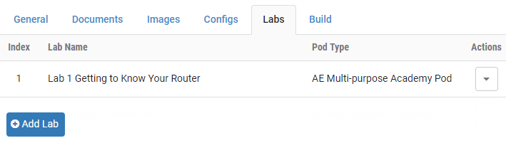
Lab exercises are displayed on the Labs tab of the lab design page. The exercises are listed in order according to the value of the index field, which may be modified as needed.
[]Creating a Lab Exercise
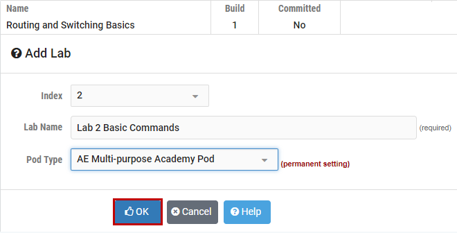
To add a lab exercise, select the Add Lab button (see picture above).
Enter a name for the lab exercise. You may find it helpful to adopt a numeric sequence as part of your naming convention to clearly indicate the order in which the lab exercises should be performed. Select the pod type for the lab; this value cannot be modified. Click OK.
Select the appropriate values for the lab exercise settings that are displayed on the next page. Each field is described below. Descriptions of each field may be displayed on the page by selecting the Help button. Enter values as needed, then select OK to save.
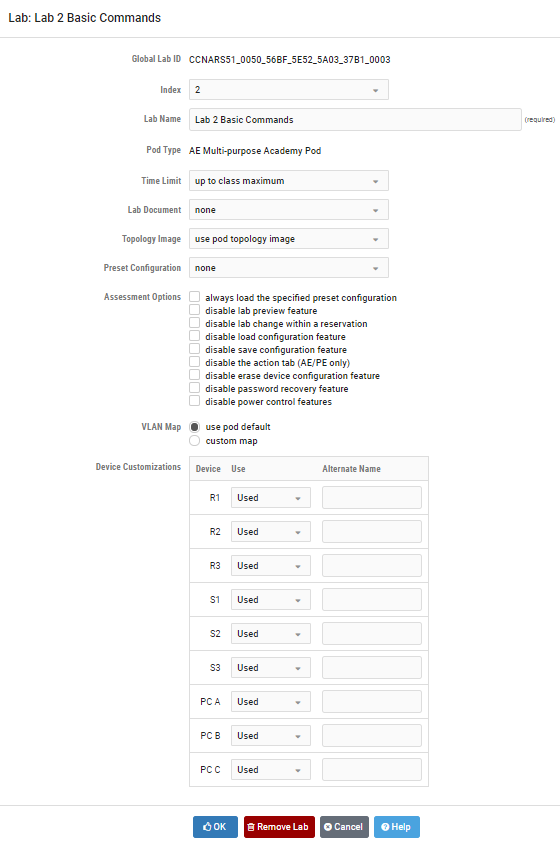
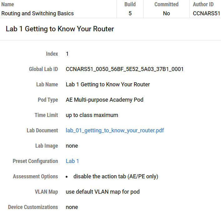
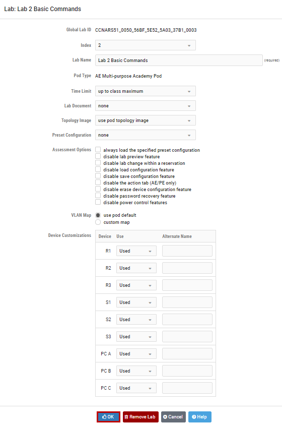
Field Descriptions – Add Lab Page
Global Lab ID: This value is the unique global identifier for this lab.
Index: The index number indicates the order in which lab exercises are listed. Accepting the default will display lab exercises in the order that they are entered into the system. Modifying the index number allows you to manipulate the order in which lab exercises are displayed. The index values of the other lab exercises present in the lab design will be updated to accommodate your modification.
Lab Name: A unique lab name must be assigned to each lab exercise.
Pod Type: Labs exercises are assigned to the appropriate pod type. Choices available will depend on the pod types currently installed on your system and may include custom pods that have been installed using the Pod Designer. Please refer to the NETLAB+ Pod Design Guide for details. The selected pod type for a lab exercise cannot be modified.
Time Limit: The amount of time that will be made available to users who make a reservation to perform the lab exercise. Please note that the actual allotted time will be 10 minutes less. The last 10 minutes are used by the NETLAB+ system to “clean up” at the end of a lab reservation.
Lab Document: A documentation file that has been added to the lab design. A lab document may be associated with more than one lab exercise. The lab document must be PDF file.
Topology Image: The image file (GIF, JPEG, or PNG format) that will be displayed on the Topology Tab when performing the lab exercise. Images may be created and added to the lab design file to reflect exercise-specific information. An image may be associated with more than one lab exercise. Alternatively, you may use the default image associated with the pod design.
Preset Configuration: This option allows the selection of a configuration folder, which contains configuration files specific to the devices in the pod that can be loaded at the start of the lab reservation. The configuration folder may be associated with more than one lab exercise.
Assessment Options: Selection of these options restrict the features made available to users during a lab reservation.
Always load the specified preset configuration: If this option is selected, preset configurations are always loaded. Otherwise, users may choose whether or not to load the configuration files at the time the lab reservation is made.
Disable lab preview feature: If selected, the lab document (instructions) cannot be previewed before the lab begins.
Disable lab change within a reservation: If selected, the exercise cannot be changed while the reservation is in progress.
Disable load configuration feature: Prevents students from loading their saved configuration files during this lab.
Disable save configuration feature: Prevents students from saving their configurations to their personal NETLAB+ file space during the lab reservation. NETLAB+ will still save their configurations in the archive at the end of the reservations.
Disable the action tab (AE/PE only): Prevents students from performing any NETLAB+ automated actions during the lab.
Disable erase device configuration feature: Prevents students from performing an automated lab reset during the lab.
Disable password recovery feature: Prevents students from performing an automated password recovery during the lab.
Disable power control features: Prevents students from control automated power outlets during the lab.
VLAN Map: This option provides a means of manipulating VLANs on NETLAB+ control switches to accommodate specific lab exercise requirements. VLAN mapping is a powerful NETLAB+ feature that allows each lab exercise to dynamically reconfigure a lab topology, thereby increasing the number of labs that can be performed on a single physical lab topology.
Use Pod Default: Each pod design has a Default VLAN Map. Selecting this setting causes the default VLAN map to be applied to the pod at the beginning of a lab reservation.
**
**
Custom map: Allow the lab exercise to specify its own VLAN map. This flexibility is called dynamic VLAN mapping. Each control switch port is given a relative port number (+0, +1, etc.) since the actual control switch ports cannot be determined at design time. Each port can have one of the following settings:

VLAN (letter): At the beginning of the lab exercise, the control switch port will be turned on and set to the VLAN indicated by the letter. The actual VLAN number used cannot be determined at design time; therefore, letters are used.
OFF: This value causes the control switch port to be turned off at the beginning of the lab exercise. It may be turned on if NETLAB+ needs to recover an erased software image.
STATIC: This value indicates that the control switch port is statically configured by the administrator. NETLAB+ will not change the administrative state (on/off), will not change the VLAN, nor any other setting on the port. Typically, you should use the static setting only if the default VLAN map in the pod design also uses static.
**
**

Device Customizations: Define device usage and alternate device names.
Usage: Designate the usage of PCs and lab devices in the lab environment.
Used: If a PC or device is Used, will operate normally in the lab environment, and can be assigned an Alternate Name, if desired.
Hidden: If a PC or device is Hidden, it will be powered on and controlled by NETLAB+, but it will not be visible and cannot be interacted with through the lab interface.
Unused: If a PC or device is Unused, it will not be powered on, and it will not be visible to the lab user. Using this setting, lab devices that aren’t required for a particular lab do not consume resources unnecessarily.
Alternate Name: Specify a name to be displayed and associated with the lab device, in place of the default name, as defined in the documentation specific to the lab exercise.
[]Modifying Lab Exercise Details
To modify any of the settings selected for a lab exercise, perform the following steps:
Select the lab exercise listed on the Labs section of the tabbed interface.
The lab exercise detail page will be displayed. Please refer to the previous section for a description of each field on the page. Field descriptions can be displayed on the page by clicking the Help button at the bottom of the page. Modify the values as needed, then select OK to save your modifications.
[]Removing a Lab Exercise
A lab exercise may be removed from the lab design by selecting the Remove Lab button on the lab exercise edit page (as shown in the previous section). If there are scheduled reservations using the lab exercise, the reservations will be modified to simple reservations with no associated exercise.
Select OK to confirm the removal of the lab exercise.
[] Relationship Between Classes, Lab Exercises, Reservations, and Pods
All lab reservations are associated with a particular class. The only exception is when an instructor chooses to reserve a pod for personal use.
The following rules determine which pods on the system are made available to a class for scheduling.
(1) Consider ONLY lab designs that are selected in the class settings.
(2) Consider ALL lab exercises resulting from rule 1.
(3) Consider ONLY the pod types required by the lab exercises determined in step 2.
(4) Consider ONLY the pods that are installed and online.
(5) Consider community-based pod rules that have been established by the administrator that may restrict access to a particular pod.
Because of rules 3 and 4, NETLAB+ will only list lab exercises for which the required pod type is available. Per rule 5, NETLAB+ may restrict access to a particular pod altogether, or at certain times.
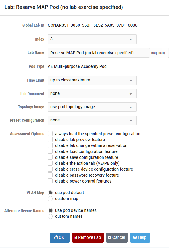
[]Creating Lab Exercises for Simple Pod Reservations
Section 3.7 outlined rules that determine which pods can be used by a class. Rule 1 and 2 imply that a class can only access a particular type of pod, if and only if the pod type is referenced in at least one lab exercise from a lab design selected for that class. Therefore, it is often desirable to create a lab exercise that allows a class to reserve a particular type of pod. This exercise will typically have no lab activity and will use the settings shown here:
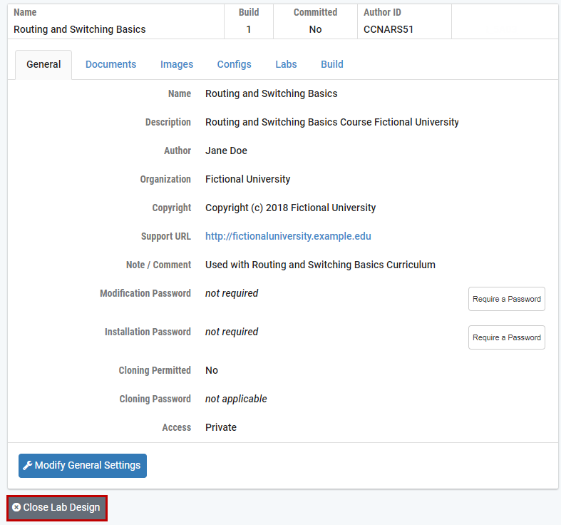
[]Closing a Lab Design
When you are done making changes to a lab design, click on the Close Lab Design button at the bottom of the tabbed interface. This will ensure that all changes are saved, and the file is unlocked.
[] Working with Lab Design Files and Builds
Lab Designer does not install lab exercises and materials directly into the NETLAB+ database. Rather, it produces an NLX file, which acts like “source code.” The lab exercises, documents, images, and preset configurations make up the source files and materials contained within an NLX file. The administrator and each instructor have a personal folder in which NLX files are stored and manipulated by the lab designer. NLX files can be exported to your PC, shared with others, and transferred to other NETLAB+ systems.
The NLX file format has built-in version control. Each version is called a build. Builds are managed from the build tab. When all desired changes have been made to the NLX file, the build is committed. Only a committed build can be installed into the NETLAB+ database, which allows the lab exercises in the lab design to be used by one or more classes.

A new build must be created to make further changes to the lab design. All changes must be made to the NLX file. You cannot directly modify lab exercises and materials in the NETLAB+ database. Therefore, it is important to export, backup, and protect your NLX files.
When you are done working with a lab design, always click on the Close Lab Design button at the bottom of the tabbed interface. This will ensure that all changes are saved, and the file is unlocked.
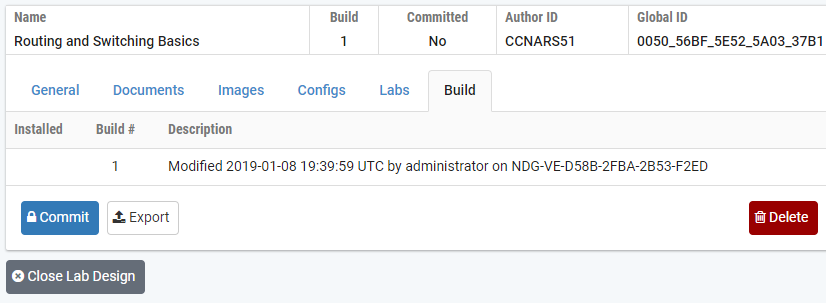
[]Build Tab
Many of the tasks described in this section are managed from the build tab. The buttons shown on the Build tab will vary depending on the state of the build, and if the NLX file is being modified.
[]Modifying a Build
To modify a build, click on the Modify Design button at the bottom of the tabbed interface. Once you are modifying a build, you can make changes to almost all of the settings contained within the design file.

If a modification password is assigned to the design file, you will be prompted to provide the correct modification password before modification is allowed.

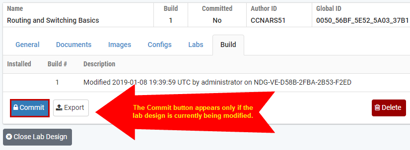
[]Committing a Build
The NLX file format has built-in version control. Each version is called a build. Builds are managed from the Build tab. After all desired changes have been made to the NLX file, the build is committed. Only a committed build can be installed into the NETLAB+ database, which allows the lab exercises in the lab design to be used by one or more classes.
To commit the current build, click on the Commit button in the Build tab.
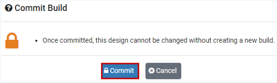
Confirm your intention to commit the build by clicking the Commit button.
After confirming the commit, further changes to the build will be locked out. You can now install the build.
[] Installing a Build
Before a lab design can be used by classes, it must be installed into the NETLAB+ database. If the current build is committed, an Install button will appear on the Build tab.
NETLAB+ will not install the current build if it is already installed.
NETLAB+ will display a warning message if you are about to install a build that is older than the currently installed build.
If the lab design requires an installation password, you will be required to enter the correct password at this time.
If the lab design was made public by the administrator, you must be the appointed trustee in order to install a new build.
To install the current build, click on the Install button located on the Build tab.

You will be prompted to confirm the install of the build.

Please note that only one instance of a lab design can only be installed on a NETLAB+ system. The global feature can be used when you wish to make your lab design available to all instructors on the system. A private lab design cannot be installed and used by more than one instructor (the trustee). However, if two or more instructors are leads in the same class, each instructor may contribute their private lab designs to the class.
[] Adding a Lab Design to a Class
Once a lab design is installed, it may be used by one or more classes. By default, a lab design is private. Only the instructor who installs a private lab design can assign it to their classes. A public lab design can be used by any class on the system.
To use a lab design in a class, select the Manage Classes option on the Manage dropdown if logged in as an instructor or select Classes on the administrator home page. Select the class that requires access to the lab design. You must be a class lead, or have appropriate rights to edit the class settings.
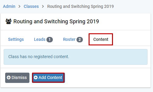
Select the Content tab on the class record and click the Add Content button.
A list of Available Lab Content is displayed. Select the checkbox for each lab design. By checking a box, you authorize the class to use the lab exercises and documents contained within. Keep in mind that access to certain pods and lab exercises is governed by the rules described in section 3.7. In the example below, the content for Routing and Switching Basics is selected for the class.

Click the Add Selected Content button. A message will confirm that the content has been added. Click OK.

[]Remove Content from a Class
To remove a lab design in a class, you must remove the content. Any class lead can remove a lab design. However, once a private lab design is removed, it can only be re-enabled by the instructor who installed it. On the Content tab, select the option to Remove Content on the Action dropdown.

[] Exporting and Backing Up Lab Design Files
The export function downloads a copy of a lab design from your personal lab design folder on the NETLAB+ system, to your local PC. You can use the export function to make a backup copy of your lab designs. Similarly, you can use the import function to restore a lab design. Import and export can be used to share lab designs with other users and/or other NETLAB+ systems. However, only one instance of a lab design can be installed per system.
To export a lab design, perform the following steps:
The Export function is available on the Build tab. Select the Export button.

The Export Design pop-up window will be displayed. To proceed, select the Begin File Download button.

The options to save the exported file will vary with your selection of browser and browser settings.
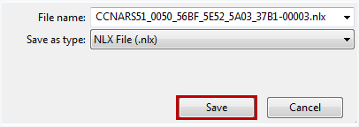
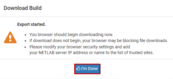
When you have completed downloading and saving the file, click the I’m Done button on the Download Build popup window.
[] Importing and Restoring Lab Design Files
The import function uploads a copy of a lab design on your local PC, to your personal lab design folder on the NETLAB+ server. Import is the opposite of export. You can use the import function to restore a backup copy of your lab designs. Import and export can be used to share lab designs with other users and/or other NETLAB+ systems. However, only one instance of a lab design can be installed per system.
To import a lab design into your NETLAB+ system, perform the following steps:
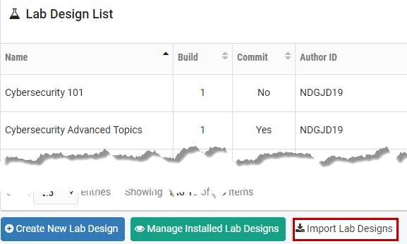
Select the Import Lab Designs button located at the bottom of the main Lab Designer page.
The Import Lab Design File popup window will be displayed. You may enter the complete path and file name, which must end with the NLX extension or proceed as shown below and select the browse button to choose a file on your machine.
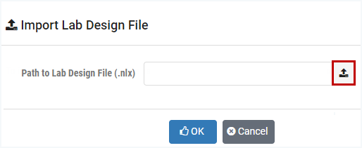
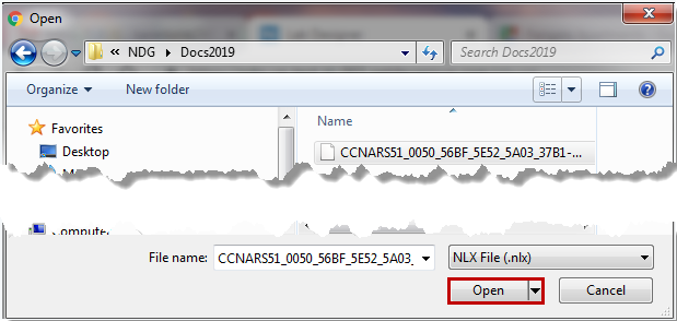
Select the path of the lab design file on your machine and then click Open.
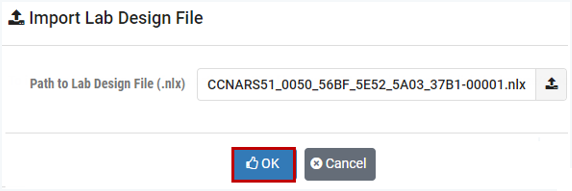
The name of the file you selected is now displayed in the Import Lab Design File popup window. Click OK to import the file.
[] Viewing a List of Installed Lab Designs
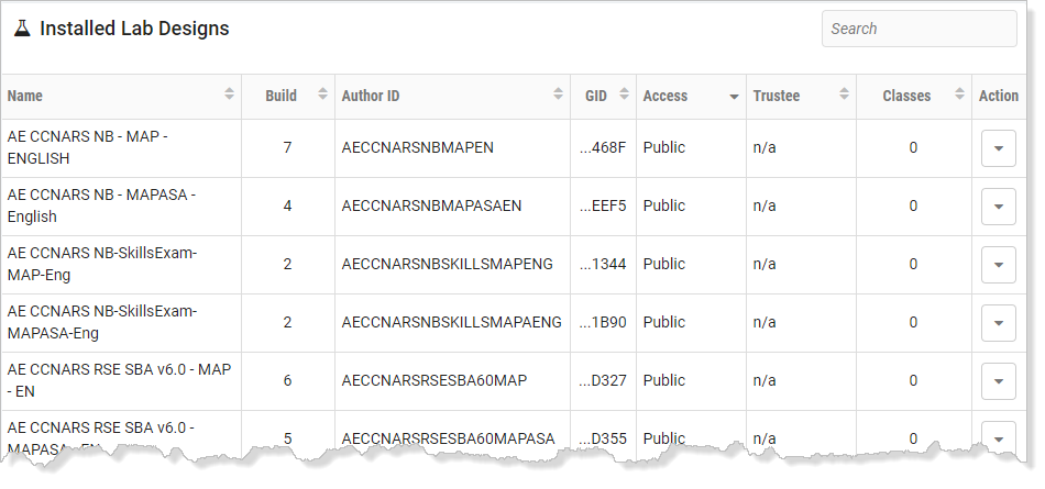
To see a list of the lab designs that are installed on your NETLAB+ system, select the Show Manage Installed Lab Designs button located at the bottom of the main Lab Designer page.
[] Making a Lab Design Public
The public setting can be used to make your lab design available to all instructors on the system. Public access is a mutual agreement between the lab designer and the system administrator. Once both parties agree to share a lab design, the administrator can appoint a trustee to manage further updates to the lab content. Only the trustee may update public content. Only the administrator may uninstall public content.
Set the access setting to Public in the general settings tab. This step is done in lab designer.

Commit the lab design and install it in the NETLAB+ database. This can be done from any instructor account or the administrator account. The lab design must be in the personal lab design folder of the account. The design will be installed privately until the administrator completes the next steps.
Open the Lab Designer tool from the administrator home page.
Click on the Show Installed Lab Designs button.
Locate and access the lab design.
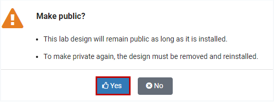
If the lab designer has completed step 1, the lab design will be eligible to be made public, and the Make Public button will appear (see the example below). Click this button and confirm.

Click Yes when prompted to confirm that you want this lab design to be made public.
[]Setting and Changing the Trustee
Only the designated trustee can install updates to a globally installed lab design. The trustee can only be changed from the administrator account. The administrator can appoint any instructor, or himself as trustee. To perform further updates, the trustee must have the lab design file (NLX) in their account’s personal lab design folder.
Perform the following steps to change a lab design’s designated trustee:
Log in to the administrator account and access the lab designer tool from the administrator home page.
Click on the Show Installed Lab Designs button.
Locate and access the lab design in the global lab designs table.
Refer to the illustration below. Click on the Change Trustee button.

Select one of the eligible trustees from the list.

[]Uninstall a Lab Design From the NETLAB+ Database
Lab designs may be uninstalled from the NETLAB+ database. Once a lab design is uninstalled, it will no longer be available for use by classes where this lab design had been selected. Select the name of the lab to uninstall from the list of installed lab designs. The Uninstall button will be displayed only if the user has the authority to delete the lab design.
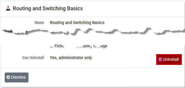
Keep in mind that once a lab design is uninstalled, it will be removed from any classes that the lab design has been selected for use. If there are scheduled reservations for lab exercises from this lab design, the reservations will be modified to simple reservations with no associated exercise.
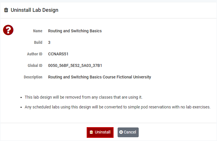
Select the Uninstall button to proceed with the uninstall of the lab design.
[] Creating a New Build
The NLX file format has built-in version control. Each version is called a build. A new build must be created to make further changes to a lab design. All changes must be made to the NLX file. You cannot directly modify lab exercises and materials in the NETLAB+ database. Once a build is committed, no further modifications may be made. In order to make additional changes to the lab design, a new build must be created.
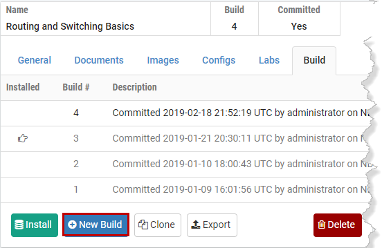
The New Build button will be available on the build tab only if the current build has been committed. Select the checkbox to remove lab design files from previous builds if you wish to have the previous builds for this lab design deleted from your lab design personal folder on the NETLAB+ server.
You may wish to keep your previous build should any circumstance cause you to decide not to proceed with the installation of the changes you plan to make to the lab design.
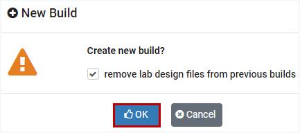
Select OK to proceed with the new build.
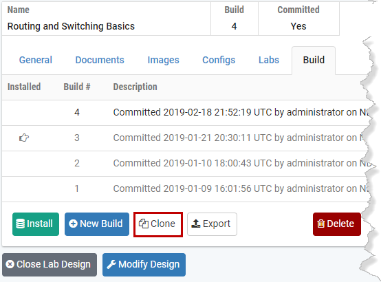
[]Cloning a Build
Use the clone feature to create derivative works based on a lab design. The cloning feature must be enabled in the general settings.
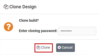
If a Cloning password requirement has been set, the password must be entered in order to proceed.
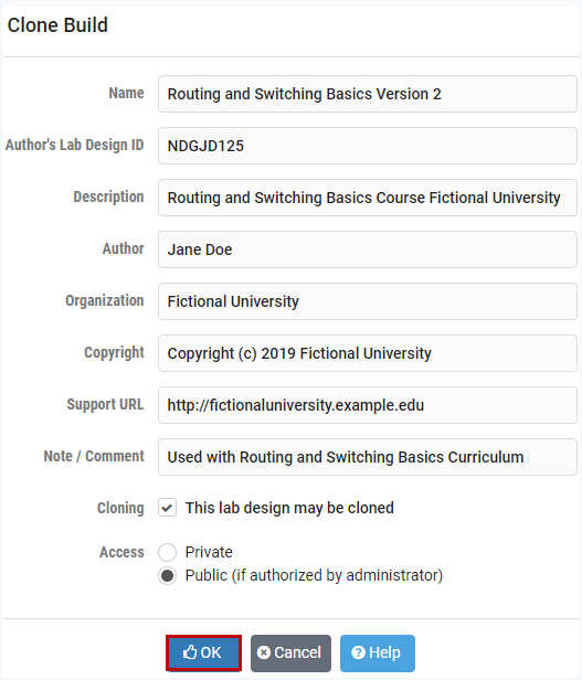
You will be required to enter a new Lab Design ID and modify the lab design name in order to create the clone. A description of the fields on the page may be displayed on the page by selecting the Help button.
[]Deleting a Lab Design from Your Personal Folder
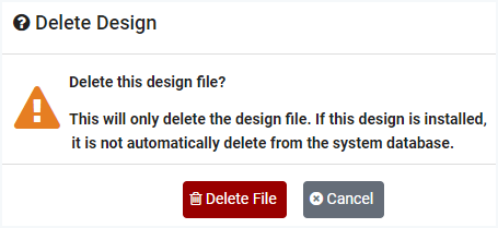
To delete a lab design file from your personal folder, select the Delete button located on the build tab.

To proceed with the deletion, select the Delete File button. Please note that deleting the design file does not automatically delete the lab design from your NETLAB+ system database.