Pod Configuration
This section walks you through the process of adding a NETLAB+ Professional Multi-Purpose Academy Pod (PMAP).
Cable the Pod
Use the diagram below to cable the NETLAB+ Professional Multi-Purpose Academy Pod (PMAP) to a control switch.
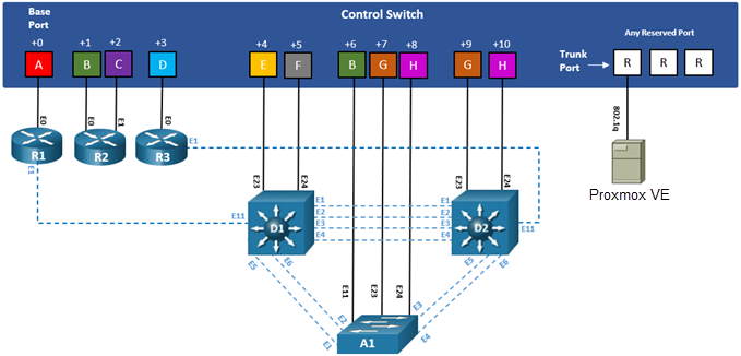
Then proceed to cable the access server lines as well as the PDU outlets; use Control Device Requirements from this guide as a reference.
NDG VMDIST Storage Connections
These storage connections should be set up and configured on your management server. Refer to Setup NDG VM Distribution System
PC Name |
VM OS |
VM ID |
VMDIST VM Name |
VMDIST Storage Connection |
|---|---|---|---|---|
PC1 |
Windows 10 Pro (64-bit) |
4211001 |
Cisco-PMAP-Win10.PC1 (build) |
vmdist.cisco.windows |
PC2 |
Windows 10 Pro (64-bit) |
4211002 |
Cisco-PMAP-Win10.PC2 (build) |
vmdist.cisco.windows |
PC3 |
Windows 10 Pro (64-bit) |
4211003 |
Cisco-PMAP-Win10.PC3 (build) |
vmdist.cisco.windows |
PC4 |
Windows 10 Pro (64-bit) |
4211004 |
Cisco-PMAP-Win10.PC4 (build) |
vmdist.cisco.windows |
Deploying from NDG VMDIST
Deploy on your management server the pod virtual machine files from the NDG VM Distribution System.
Navigate to your Proxmox VE Management Server using your management workstation in a web browser.
Using your navigation panels, navigate to Resource Tree > Datacenter > your_management_server > vmdist.cisco.windows.
In the Content Panel, select Backups.
In the Notes column, select the name Cisco-PMAP-Win10.PC1.
Note
These build numbers may vary. Please refer to the Release Notes of the content to determine the latest version.
Click the Restore button.
In the Restore: VM popup window, select your Storage (i.e. NETLAB1).
Set the VM field to 4211001.
Click the Restore.
Proxmox VE will begin deploying the virtual machine. This may take some time, depending on the speed of your connection, HDDs, etc. Repeat the previous steps for each remaining virtual machine in the pod from the table above.
Modify Virtual Machines
Once the virtual machines are imported onto the management host, verify the configurations. The following steps will guide you through the process.
Create a Snapshot
Locate the Cisco-PMAP-Win10.PC1 virtual machine. In the Content Panel, select Snapshots.
Click the Take Snapshot button.
In the Create Snapshot window, type GOLDEN. Click Take Snapshot to take a snapshot.
Repeat these steps for each virtual machine.
Virtual Machine Credentials
For your reference, the following table provides a list of the credentials for the systems in the pod:
Machine |
Username |
Password |
|---|---|---|
PC1 |
sysadmin |
Train1ng$ |
PC2 |
sysadmin |
Train1ng$ |
PC3 |
sysadmin |
Train1ng$ |
PC4 |
sysadmin |
Train1ng$ |
Provide Temporary Internet Access to PC1, PC2, PC3, and PC4
Navigate to your Proxmox VE management server using your management workstation, and login.
Using your navigation panels, navigate to Resource Tree > Datacenter > your_management_server.
Expand its view to see the virtual machines you previously deployed.
Locate the PC1 virtual machine. In the Content Panel, select Hardware.
Select Network Device (net0) and click the Edit button.
In the Edit: Network Device window, set the Bridge field to an internet-accessible bridge.
Note
Alternatively, you can add a new Network Device to the VM and use it to link to a virtual machine port group that is linked to an internet accessible physical adapter.
Click OK to confirm the changes.
Repeat these instructions for the PC2, PC3, and PC4 virtual machine(s).
License and Activate PC1, PC2, PC3, and PC4
Select PC1 virtual machine and click the Start button in the upper right.
Click the down arrow next to the Console button in the upper right, and select noVNC.
Log on to the PC1 virtual machine in the pod. If necessary, click the dropdown arrow for the VM’s tab
and select Send CTRL+ALT+DEL.
Log in as sysadmin with Train1ng$ as the password.
Once logged in, make sure the TCP/IP settings are temporarily configured correctly so that the internet is reachable. This can vary depending on how your environment is set up.
Note
If you added a new temporary Network Device from the previous section, make sure to configure the TCP/IP settings for the newly added network adapter and use it to connect out to the internet.
Right-click on the Start icon in the lower-left and select System.
Scroll down and click Change product key or upgrade your edition of Windows in
the Windows activation section.
Click Change product key in the Activate Windows Now section.
Enter the product key and follow the on-screen instructions.
Windows should now be activated. If you received an error, make sure that the key entered is valid and
click the Troubleshoot link from the Activation Settings to troubleshoot the problem.
Repeat these instructions for the PC2, PC3, and PC4 virtual machine(s).
Shut Down PC1, PC2, PC3, and PC4
While on the PC1 machine, click the Start menu followed by clicking
the Shut Down button.
Repeat these instructions for the PC2, PC3, and PC4 virtual machine(s).
Reset the NIC to SAFETY_NET
Navigate to your Proxmox VE management server using your management workstation, and login.
Using your navigation panels, navigate to Resource Tree > Datacenter > your_management_server.
Expand its view to see the virtual machines you previously deployed.
Locate the PC1 virtual machine. In the Content Panel, select Hardware.
Select Network Device (net0) and click the Edit button.
In the Edit: Network Device window, set the Bridge field to SAFETY_NET.
Note
If you added a new temporary Network Device from the previous section, make sure to remove the Network Device.
Click OK to confirm settings.
Repeat these instructions for the PC2, PC3, and PC4 virtual machine(s).
Take Updated Snaphots
Locate the PC1 virtual machine. In the Content Panel, select Snapshots.
Select the current GOLDEN snapshot and click Remove.
Remember the name of this snapshot, as the new snapshot will need to have the exact same name.
Click Yes on the Confirm window.
Click the Take Snapshot button.
In the Create Snapshot window, type GOLDEN or whatever prior snapshot name the virtual machine had.
Click Take Snapshot to take a snapshot.
Repeat these steps for each virtual machine.
NETLAB+ Virtual Machine Inventory Setup
This section will guide you in adding your master virtual machines to the Virtual Machine Inventory of your NETLAB+ VE system.
Log in to your NETLAB+ VE system using the administrator account.
Select the Virtual Machine Infrastructure icon.
Click the Virtual Machine Inventory icon.
Click the Import Virtual Machines button located at the bottom of the list.

Select the appropriate datacenter from the list where your VMs reside.
Select the checkbox next to the virtual machines you have just deployed and click Import Selected Virtual Machines.

When the Configure VMs window loads, you can set your virtual machine parameters.
Note
It is advised to leave the Version and Build numbers for reference when requesting NDG support.
Check the dropdown box for the correct operating system for each imported virtual machine.
Change
RoletoMasterfor each VM.Add any comments for each virtual machine in the last column.
Verify your settings and click
Import (X) Virtual Machines(notice the number in parenthesis is dynamic, depending on the amount of VMs selected).Verify all
Import Statusesreport back withOKand then click on theDismissbutton.Verify that your virtual machines show up in the inventory.
For additional information, please refer to the NETLAB+ VE Administrator Guide.
Create Full Clone Templates on Host Server
Log in to your NETLAB+ VE system using the administrator account.
Select the Virtual Machine Infrastructure icon.
Click the Virtual Machine Inventory icon.
Select PC1 from the list of virtual machines.
Scroll to the bottom and click the Clone button.
Set the Parent Snapshot field is pointing to the snapshot taken in Take New Snapshots.
Set the Clone Name field to a valid name.
Note
NDG recommends you name this virtual machine with the following format for clarity and ease of troubleshooting: i.e. H21-TEMPLATE.MDP.PC1
Set Clone Role to Template.
Set Runtime Host or Group to your host server. This should NOT be your management server.
Set Datastore to the storage of your choice. This should be NETLAB1 or NETLAB2 etc, if you have multiple drives.
Click the Clone button.
Repeat these instructions for the PC2, PC3, and PC4 virtual machine(s).
Enabling Labs in Course Manager
Please refer to the Course Manager section of the NETLAB+ VE Administrator Guide on how to enable content. Please install the desired Cisco course.
Create the NETLAB+ Professional Multi-Purpose Academy Pod (PMAP)
Log into NETLAB+ VE with the administrator account.
Select the Pods icon.

Create a new pod by scrolling to the bottom and clicking the Create New Pod button.

Then, click on the AE Multi-Device Pod pod entry from the list of installed pod types.
On the New Pod window, input a value into the Pod ID and Pod Name fields. Click Next.
Note
The Pod ID determines the order in which the pods will appear in the scheduler. It is best practice to use a block of
sequential ID numbers for the Pod Id that allows for the number of pods you are going to install.
The Pod Name identifies the pod and is unique per pod. Here we used the name of the lab set or course in a shortened form.
To finalize the wizard, click OK.
For additional information, please refer to the NETLAB+ VE Administrator Guide.
Create Link Clone VMs on Host Server
Select the Virtual Machine Infrastructure icon.
Click the Virtual Machine Inventory icon.
Select the Full Clone Template VMs you created in Create Full Clone Templates from the list of virtual machines.
Scroll to the bottom and click the Clone button.
Set the Clone Name field to a valid name.
Note
NDG recommends you name this virtual machine with the following format for clarity and ease of troubleshooting: i.e. H21-MDP.P01.PC1
Set Clone Type to Linked Clone.
Set Clone Role to Normal.
Click the Clone button.
Repeat these instructions for the PC2, PC3, and PC4 virtual machine(s).
Attach Link Clone VMs to the Pod
Update the pod to associate the virtual machines with the newly created pod.
Select the NETLAB+ Professional Multi-Purpose Academy Pod (PMAP) pod from the pod list.
In the pod view, click on the Remote PC tab. Proceed by then clicking on the Action dropdown next to the
virtual machine you are about to assign and select Attach VM.
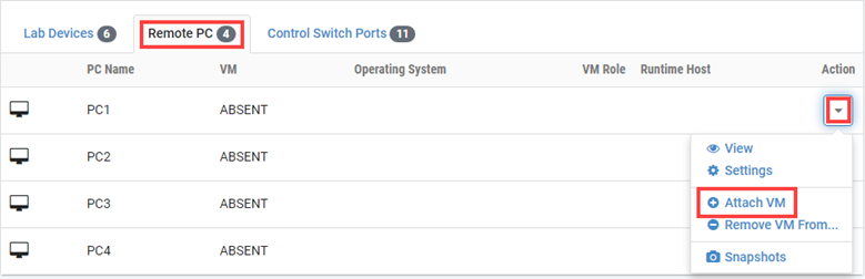
Select the corresponding virtual machine from the inventory list.
Click OK to confirm the VM attachment and repeat the previous steps for the remaining virtual machines.
Create Snapshots for Link Clone VMs
In order to proceed with pod reservations, snapshots must be created on each of the pod’s virtual machines.
Warning
Verify that all VMs are still powered off before taking snapshots.
Make sure to view the NETLAB+ Professional Multi-Purpose Academy Pod (PMAP) you just assigned machines to.
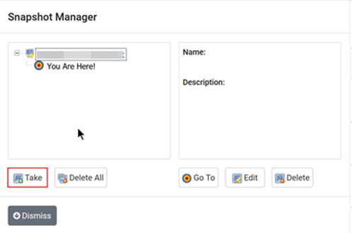
In the pod view, click on the dropdown menu option underneath the Action column for a specific VM and select Snapshots.
In the Snapshot Manager window, click on the Take button. This will take a snapshot of the current state of the virtual machine.
Warning
Any changes made after this will require a new snapshot or those changes will not reflect in the reset state of the pod or its clones.
In the Take Snapshot window, type GOLDEN into the Name text field, or you may choose another naming
convention as long as it is consistent for easy management. Click OK to take the snapshot.
Warning
It is recommended to use GOLDEN as the snapshot name when working with normalized pod types.
In the Snapshot Manager window, notice the snapshot is created. Click the Dismiss button.
Warning
At this point it is good to verify that you have only one snapshot on the virtual machine. Multiple snapshots increase the likelihood of having problems, especially if the snapshots are named the same. Also, the more snapshots a virtual machine has, the slower the performance and the more drive space is used.
Repeat the previous steps for the remaining virtual machines.
Set the Revert to Snapshot
Make sure to view the NETLAB+ Professional Multi-Purpose Academy Pod (PMAP) master pod you just created snapshots for. In the pod view,
click on the dropdown menu option underneath the Action column and select Settings.
In the virtual machine’s Settings window, click on the Revert to Snapshot dropdown and select GOLDEN and then click the Submit button.
Note
This sets the snapshot on the virtual machine that will get reverted to each time the pod is scheduled.
Click OK to confirm.
Return to the pod view page and repeat the previous steps for the remaining virtual machines.
Select Control Switch and Ports
A NETLAB+ Professional Multi-Purpose Academy Pod (PMAP) requires 11 consecutive control switch ports. NETLAB+ will present a list of the control switches on your system. Switches that meet the port requirement can be selected. Choose one control switch for your new pod.
Note
If no control switches have been added to your NETLAB+, you may reference the Real Equipment Pod Installation Guide for instructions on how to add new control devices.
Make sure to view the NETLAB+ Professional Multi-Purpose Academy Pod (PMAP). In the pod view, click on the Control Switch Ports
tab and then click on the Action dropdown menu for the first entry, followed by clicking Assign Control Port.
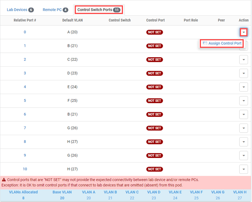
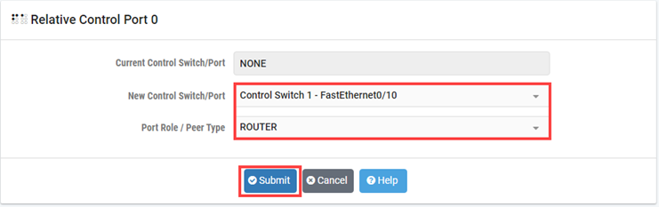
Choose the control switch port and identify the correct port role type. Click Submit.
Note
When configuring the control switch ports, refer to Control Device Requirements to identify the respective Relative Port # and Base Port numbers along with the Port Role based on the lab device.
Once configured by NETLAB+, click Dismiss to proceed.
Return to the pod view page and repeat the previous steps for the remaining control switch ports.
Select Device Types, Access Server & PDU Ports
A NETLAB+ Professional Multi-Purpose Academy Pod (PMAP) requires 6 access server lines.
It is a good idea to use consecutive lines on one access server if possible. This practice will make it easier to cable and troubleshoot. If consecutive ports are not available, you can use non-consecutive ports on different access servers if necessary.
NETLAB+ allows you to choose consecutive lines on one access server, or you can choose to select an access server and line for each router.
Note
If no access servers have been added to your NETLAB+, you may reference the Real Equipment Pod Installation Guide for instructions on how to add new access servers.
A NETLAB+ Professional Multi-Purpose Academy Pod (PMAP) requires 6 outlets.
It is a good idea to use consecutive outlets on one power distribution unit if possible. This practice will make it easier to cable and troubleshoot. If consecutive outlets are not available, you may use non-consecutive outlets, spanning multiple SODs if necessary.
Note
If no PDUs have been added to your NETLAB+, you may reference the Real Equipment Pod Installation Guide for instructions on how to add new PDU devices.
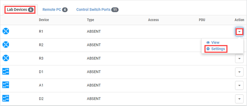
Make sure to view the NETLAB+ Professional Multi-Purpose Academy Pod (PMAP). In the pod view, click on the Lab Devices tab
and then click on the Action dropdown menu for the first entry, followed by clicking Settings.
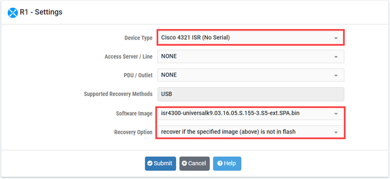
First, choose the appropriate device type in relation to the specific Cisco model being used as well as its respective software image to be used for NETLAB+ recovery. Make sure to select a recovery option.
Note
Device type selections are used to assign the appropriate NETLAB+ device drivers. Improper selections may cause errors.
NETLAB+ scrubs each router at the end of lab reservation or upon request. During a scrub, NETLAB+ can recover an IOS image if it is erased from flash.
Note
If no lab device images have been added to your NETLAB+, you may reference the Real Equipment Pod Installation Guide for instructions on how to add new lab device images.
You have three choices for flash recovery:
Recovery Using Specified Image |
During A Scrub Operation… |
|---|---|
recover if the specified image (above) is not in flash |
Restores the selected software image if that image is not in flash. |
recover if there is no image in flash |
Restores the selected software image if there are no .bin images in flash. No action is taken if flash contains
a |
never recover image (device may become unusable) |
NETLAB+ will take no action if the flash does not contain a bootable image. In this case, the NETLAB+ automated boot process will fail, and manual restoration of IOS will be required. |
Warning
If you select an automatic recovery option, you must also select a software image supported by the curriculum.
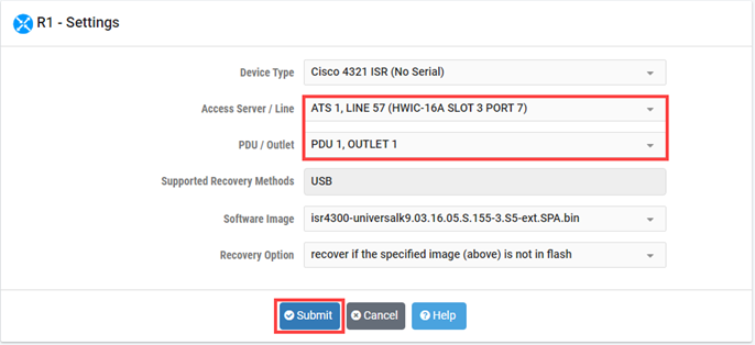
Then choose the line number for the access server line connected, followed by the PDU outlet being used.
Once finished, click Submit.
Note
The options available here allows you to make granular selections. For access servers using octal cables, both the line number and the cable label are displayed.
Click OK and repeat the previous steps for the remaining lab devices in the pod.